
Description
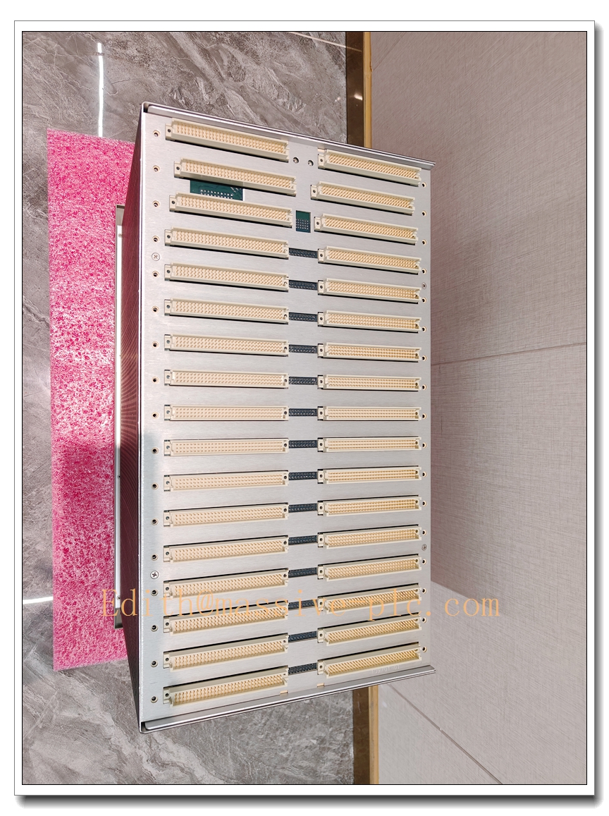
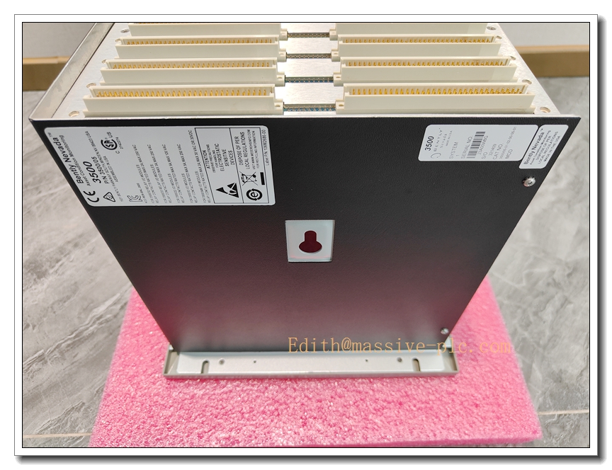
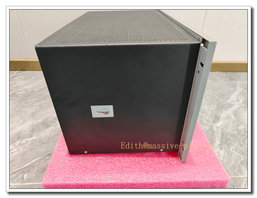
Bently‑Nevada 3500/05‑01‑01‑00‑00‑01 System Rack Chassis
Product Description
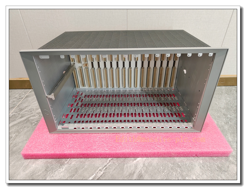
The 3500/05‑01‑01‑00‑00‑01 is the full‑size 19‑inch panel‑mount system rack chassis for Bently‑Nevada 3500‑M‑series machinery‑protection system. It provides mechanical housing, backplane bus, power distribution and inter‑module high‑speed communication infrastructure for all 3500 series monitor, relay, communication, TDI and power‑supply modules.
This chassis itself contains no measurement or logic circuitry. The integrated high‑reliability backplane routes DC power, backplane data bus and system grounding for every plugged‑in module. Left‑hand dedicated slots are reserved for power‑supply units and the 3500/22 TDI gateway; remaining slots accept full‑height / half‑height adapters for flexible module population. The suffix‑01 indicates CE European compliance certification. OEM manufacturing is discontinued; available only as aftermarket replacement spare for legacy turbomachinery TSI installations.
Order code breakdown: 3500/05‑AA‑BB‑CC‑DD‑EE
- AA=01:Full‑size 19‑inch rack, total 14 full‑height module slots
- BB=01:Panel‑mount installation style
- CC=00:No additional third‑party agency safety approval
- DD=00:Reserved field
- EE=01:CE compliance mark
3500/05‑01‑01‑00‑00‑01
Technical Specifications
| Item | Specification |
|---|---|
| Complete Part Number | 3500/05‑01‑01‑00‑00‑01 |
| Rack Type | Full‑size 19‑inch system rack chassis |
| Total Full‑height Slots | 14 slots (2 reserved for power supply, Slot 1 fixed for TDI) |
| Mounting Method | Panel‑mount (cabinet cut‑out installation) |
| Backplane Interface | Parallel backplane bus for power, data communication and system grounding |
| Supported Modules | 3500‑M series full‑height modules; supports half‑height modules via adapter kit(125388‑01) |
| Certification | CE compliance; no CSA / ATEX agency approvals for this ordering option |
| Material | Heavy‑duty aluminum alloy industrial chassis |
| Overall Dimension(W×H×D) | 483 mm × 445 mm × 349 mm (19.0 in × 17.5 in ×13.75 in) |
| Approximate Net Weight | 4.5 kg (9.92 lbs) |
| Operating Temperature | ‑30 °C ~ +65 °C (‑22 °F ~ +149 °F) |
| Storage Temperature | ‑40 °C ~ +85 °C (‑40 °F ~ +185 °F) |
| Relative Humidity | 5‑95 % RH, non‑condensing |
| Hot‑swap Support | Backplane design permits hot‑swap of individual plug‑in modules (power supply, monitor, relay, gateway) |
| Product Status | Discontinued OEM production, aftermarket spare‑part only |
Key Features & Benefits
- Complete system mechanical & bus infrastructure: Unified chassis delivers power distribution and high‑speed inter‑module backplane communication, supporting vibration, thrust, speed, temperature, process‑variable monitoring, relay interlock and transient‑data acquisition within one single rack assembly.
- Flexible slot allocation architecture: 14 full‑height positions; dedicated left‑side slots for redundant power‑supplies and mandatory TDI gateway. Other slots can freely mix monitor, relay‑output and communication‑gateway modules; half‑height modules are usable with optional adapter hardware.
- Hot‑swap capable backplane design: Field‑replaceable modules can be inserted / extracted under rack powered‑on state (subject to individual module specification), minimising system downtime during spare‑part maintenance.
- Robust industrial mechanical construction: Vibration‑resistant aluminium chassis optimised for turbomachinery cabinet environments; integrated noise‑suppressed grounding layout reduces ground‑loop interference risk for intrinsic‑barrier applications (works together with 3500/04 earthing module for internal‑barrier configurations).
- Full backward‑compatibility: Compatible with all 3500‑M‑series front‑main‑board plus rear‑I/O assemblies, legacy rack firmware and 3500 configuration software. Supports non‑redundant / dual‑redundant power‑supply deployment.
- CE‑compliant panel‑mount form factor: Designed for cabinet cut‑out panel‑mount installation, typical for power‑generation, oil‑gas and petrochemical control‑cabinet layouts.
Application Fields
- Turbomachinery machinery‑protection systems for steam turbines, gas turbines, centrifugal & axial compressors in power‑plant, refinery and natural‑gas processing facilities. Houses 3500‑M‑series monitors, TDI transient‑data gateway, relay‑output modules, Modbus‑gateway and redundant power‑supply assemblies.
- Legacy‑system retrofit and spare‑chassis replacement for existing 3500‑M installations requiring 19‑inch panel‑mount rack with CE marking, no additional third‑party hazardous‑area agency certification.
Related Recommended Products
- 3500/15 series: AC / DC rack power‑supply modules (install at far‑left dedicated slots)Baker Hugh…
- 3500/22‑01‑01‑00: TDI Transient Data Interface (must occupy Slot 1)
- 3500‑M monitor family: 3500/40M, 3500/42M, 3500/50, 3500/60, 3500/62 monitor assemblies
- 3500/32‑01‑00: Relay‑output assembly for alarm & trip interlock
- 3500/92 series: Modbus communication gateway modules
- 125388‑01: Half‑height‑module adapter kit for mixing half‑height modules inside full‑size rack
- 3500/04‑01: Internal‑barrier grounding module for 3500/04 intrinsic‑safety barrier configurations
- 3500 Rack Configuration Software: System commissioning and parameter download tool
Installation and Maintenance
Installation
- Perform cabinet cut‑out according to official mechanical drawing, secure the 3500/05 chassis into control‑cabinet by panel‑mount fasteners.
- Complete protective earth connection to rack designated grounding terminal; for internal‑barrier hazardous‑area setup, install matching 3500/04‑01 barrier earthing module and follow intrinsic‑safety grounding requirements strictly.
- Insert power‑supply modules into dedicated far‑left slots; insert TDI‑TDI assembly to fixed Slot 1. Populate remaining slots with monitor, relay and gateway assemblies as per project design.
- Mount blank filler panels for unused slots to guarantee proper airflow and EMC performance.
- Apply input power to power‑supply units, verify rack backplane health status via TDI front‑panel LED and rack event‑log.
Important Note: The 3500/05‑01‑01‑00‑00‑01 chassis is purely passive mechanical‑backplane hardware; it cannot run any protection or monitoring function without power‑supply, TDI and corresponding monitor modules. Power‑supply and TDI must occupy their dedicated reserved slots.
Maintenance
- Periodically inspect rack mechanical fasteners, protective‑earth connection condition, and filler‑panel completeness. Keep cabinet ventilation pathways free from dust accumulation.
- When replacing plug‑in modules, follow each module’s hot‑swap specification; do NOT remove power‑supply or TDI while rack is running unless required by maintenance procedure.
- Inspect backplane connector pins for dust or corrosion whenever modules are withdrawn. Avoid mechanical shock to chassis and backplane during module insertion.
- Refer to official Bently‑Nevada document 129766 (3500/05 Rack Installation Manual) for full mechanical dimensions, mounting cut‑out drawing, grounding rules and troubleshooting guidance.


 Start Chat




