
Description
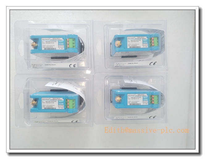
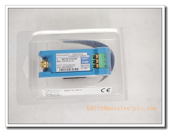
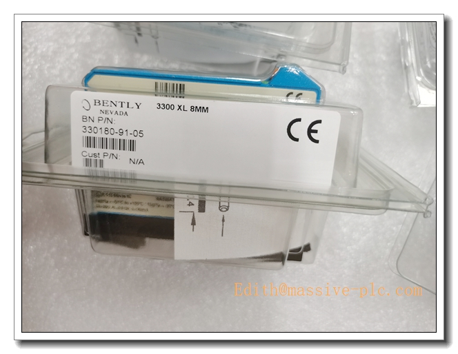
Bently Nevada 330180‑91‑05 — 3300‑XL 5/8 mm Proximitor® Sensor
Product Overview
The 330180‑91‑05 is a 9‑meter total‑system‑length Proximitor® sensor from Bently Nevada 3300‑XL 5/8 mm eddy‑current transducer family. It features DIN‑rail mounting and multi‑hazardous‑area certifications. As the signal‑conditioning core of non‑contact proximity measurement loops, it converts impedance variation between probe tip and metallic shaft target into calibrated DC gap‑voltage output for static position and dynamic vibration monitoring, fully compliant with API 670 turbomachinery protection standards.
Compared with 330180‑51‑05 (5 m version), this unit supports 9‑meter total system cable length, ideal for field sites with long physical distances between machine probes and instrument cabinet racks.
330180-91-05
Specific Application Information
Paired with matched 3300‑XL proximity probe and extension cable, it executes non‑contact measurement for rotating metallic shafts:
- Radial shaft vibration: AC component of output captures shaft vibration amplitude for journal‑bearing health monitoring.
- Axial thrust / shaft position: DC gap‑voltage monitors static thrust‑shaft displacement to detect thrust‑bearing wear and failure risk.
- Keyphasor® phase reference & rotational speed: Works with notch‑type probe to generate tachometer pulse for RPM calculation and machine phase analysis.
- Long‑distance field retrofit: Drop‑in spare for legacy 3300‑XL systems requiring 9‑meter full‑system cable length, solving long wiring distance constraints between field machine and control cabinet.
Key Specifications
| Parameter | Value |
|---|---|
| Part Number | 330180‑91‑05 |
| Series | 3300‑XL 5/8 mm (8 mm) Proximitor Sensor |
| Total System Length | 9 m (29.5 ft) |
| Mounting Style | DIN‑rail mounting; also compatible with bulkhead screw mounting |
| Scale Factor | 7.87 V/mm (200 mV/mil) for AISI‑4140 steel target |
| Linear Measurement Range | 2.0 mm (80 mils) |
| Frequency Response | 0 Hz ~ 10 kHz |
| Power Supply | ‑17.5 VDC ~ ‑26 VDC, ≤14 mA consumption |
| Operating Temperature | ‑35 °C ~ +85 °C (T5); ‑51 °C ~ +100 °C (T4) |
| Output Signal | Proportional DC gap‑voltage; coaxial PROX‑OUT auxiliary dynamic output |
| Certifications | CE, ATEX, IECEx, CSA Class I Div 2, Ex ia IIC / Ex na IIC hazardous‑area approvals |
| Calibration Target | Factory calibrated for AISI‑4140 steel |
| Country of Origin | USA |
| Weight | ≈0.40 kg |
Main Features
- 9‑meter matched total‑system length: Specifically designed for sites with long wiring run between field probe and control cabinet; strict full‑system length matching eliminates scale‑factor deviation.
- API‑670 compliance: Optimized for turbomachinery protection, delivers stable linear gap‑voltage output under industrial disturbance.
- Dual‑mount mechanical design: Clip‑on 35 mm DIN‑rail for high‑density cabinet layout; bulk‑head mounting holes for legacy‑footprint retrofit projects.
- Built‑in diagnostic logic: Not‑OK / Signal‑Defeat circuit suppresses false alarms caused by open probe, short‑circuit or loose coaxial connectors; Power‑Up Inhibit avoids false trips during power‑on transient.
- Dual signal outputs: Terminal‑block DC gap‑voltage for monitor rack; coaxial PROX‑OUT port outputs raw dynamic vibration waveform for oscilloscope or portable diagnostic instrument.
- Potted rugged construction: Resists humidity, shock and cabinet‑level vibration, suitable for petrochemical, power‑plant and offshore environments.
- Test‑input pin: Supports loop simulation test via function generator, no mechanical adjustment on machine shaft required during commissioning check.
- Intrinsic‑safety hazardous‑area ratings: ATEX / IECEx Ex ia IIC certification for installation in Zone 0 / Zone 1 hazardous locations.
- Integrated isolation base: 500 Vrms isolation between unit and DIN‑rail, removes extra insulating mounting plate requirement.
330180-91-05
Typical Application Scenarios
- Steam / gas turbine machinery protection for power‑generation plants with long field‑to‑cabinet wiring distance
- Centrifugal compressors in refinery, petrochemical and LNG facilities
- Large critical pumps, fans, blowers and fluid‑film‑bearing motors
- Off‑shore platform rotating‑machinery condition‑monitoring loops
- Pulp‑and‑paper, steel‑mill heavy rotating‑equipment safety monitoring
- Hazardous‑area classified sites requiring ATEX / IECEx intrinsic‑safety certification
- Retrofit and spare‑part replacement for existing 9‑m 3300‑XL proximity measurement loops
Related & Recommended Alternative Models
| Model | Description |
|---|---|
| 330180‑51‑05 | 3300‑XL proximitor, 5 m total‑system length, DIN‑rail mount, multi‑hazardous‑area approvals |
| 330180‑90‑05 | 3300‑XL proximitor, 9 m total‑system length, panel‑mount version, multi‑approvals |
| 330180‑92‑05 | 3300‑XL proximitor, 9 m total‑system length, no mounting hardware, multi‑approvals |
| 330180‑91‑00 | 3300‑XL proximitor, 9 m length, DIN‑rail mount, basic version without hazardous‑area certifications |
| 330780‑xx‑xx | 3300‑XL 11 mm large‑gap proximitor family for larger target clearance demand |
Compatible Components & Accessories
- 3300‑XL 8 mm proximity probes: e.g. 330103‑00‑06‑10‑02‑00, 330104‑xx‑xx‑xx‑xx‑xx series; must be used within 9‑meter total‑system configuration.
- Matched 3300‑XL extension cables: 330130‑xx‑xx‑00 series; probe cable + extension cable total length = 9 m.
- Bently Nevada monitor modules: 3500/42M, 3300/12, 3300/15 monitor racks for gap‑voltage acquisition, alarm and trip logic.
- Shielded twisted‑pair field wiring: 22 AWG shielded cable for power and signal; single‑end shield grounding only at monitor‑rack side.
- 35 mm standard DIN‑rail: for cabinet DIN‑clip installation.
- Calibration test fixture: static gap‑calibration tool for commissioning and periodic maintenance verification.
Installation and Configuration Guide
Warning: Installation must be performed by qualified instrumentation technicians. Always refer to original Bently Nevada 3300‑XL official user manual as primary authority.
- Mechanical Mounting
- Install proximitor inside clean, ventilated instrument cabinet; avoid mounting beside high‑power contactors or variable‑frequency drives to minimize EMI interference.
- Snap unit onto standard 35 mm DIN‑rail or fasten through bulk‑head mounting holes. Ensure isolation base is fully seated; reserve peripheral clearance for heat dissipation.
- 9‑Meter System‑Length Matching
- Verify that the sum of probe‑cable length plus extension‑cable length equals exactly 9 meters, the rated total‑system length of 330180‑91‑05. Any length mismatch will produce measurement deviation.
- Torque coaxial connectors to manufacturer‑specified torque value; avoid over‑tightening. Do not connect / disconnect coaxial cables while power is applied.
- Electrical Wiring
- Supply negative‑polarity DC power: ‑17.5 VDC ~ ‑26 VDC to power terminals. Positive‑polarity supply will permanently damage the proximitor.
- Deploy shielded twisted‑pair for power and signal wiring. Connect cable shield only at monitor‑rack end, leave shield floating at proximitor side to eliminate ground‑loop noise.
- Terminate PROX‑OUT coaxial port to diagnostic instrument when dynamic waveform capture is needed; cap unused PROX‑OUT connector.
- Commissioning & Gap‑Voltage Adjustment
- Adjust mechanical probe installation gap to nominal mid‑range working point (target gap voltage approx. ‑10 VDC for AISI‑4140 steel target).
- Measure DC gap‑voltage between SIG and COM terminals with high‑impedance multimeter, confirm operating point lies within linear zone (‑1 VDC ~ ‑17 VDC).
- Perform static gap calibration; validate Not‑OK fault indication by simulating probe open‑circuit failure.
- System Integration
- Feed DC gap‑voltage output to Bently Nevada monitor channel. Configure monitor scale factor to 7.87 V/mm. Set alarm and trip thresholds following machinery OEM specification.
- Use Test‑Input pin to inject simulated gap signal for loop‑function test without machine intervention.
- Maintenance & Troubleshooting
- Periodically inspect coaxial connections for looseness or corrosion.
- Monitor Not‑OK status flag; Not‑OK assertion indicates failure of probe, extension cable or connector.
- Internal potted assembly cannot be repaired in‑field; replace complete unit upon hardware fault.
- Hazardous‑Area Special Requirement
- For Ex ia IIC hazardous‑area installation, strictly comply with ATEX / IECEx rules for cable type, grounding and enclosure rating.
Supplementary Remark
330180‑91‑05 is mature 3300‑XL series hardware, widely used as spare‑part for global existing turbomachinery assets. For new‑build projects, check Bently Nevada latest part‑number migration notice. Before site deployment, cross‑verify nameplate marking, total‑system‑length marking and agency approvals.


 Start Chat




