
Description
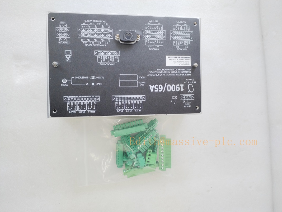
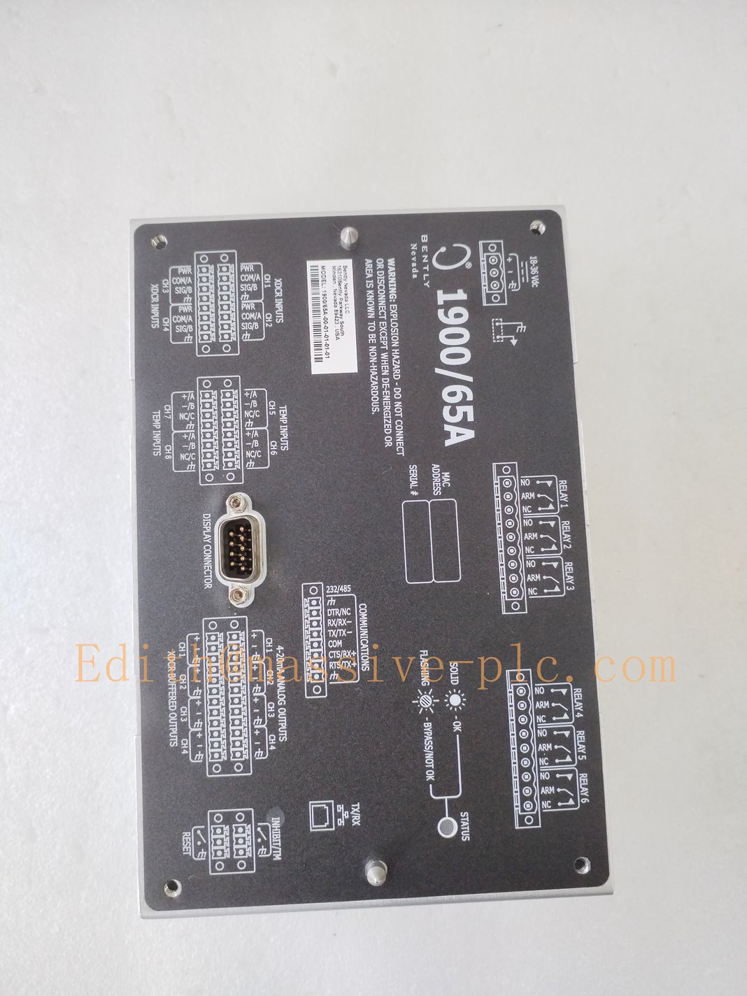
Bently Nevada 1900/65A General Purpose Equipment Monitor
Model Introduction
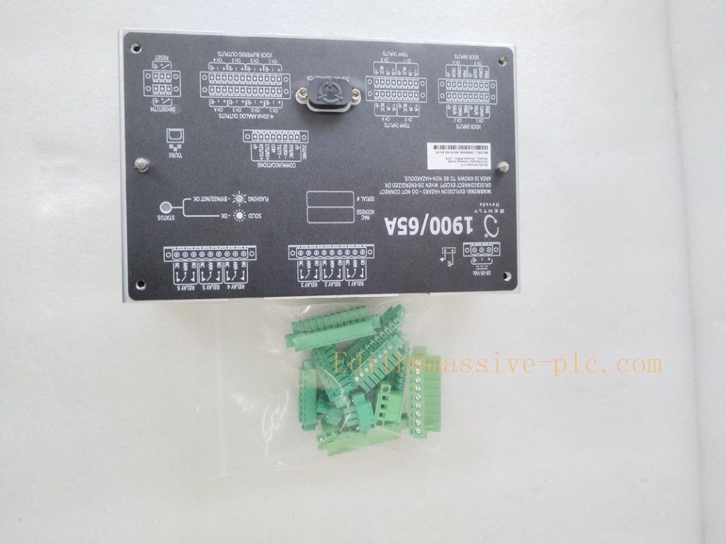
Model: 1900/65A General‑Purpose Equipment Monitor Part Number:1900/65A (full ordering code example:1900/65A‑01‑00‑01‑00‑00) Device Type: Stand‑alone panel‑mount multi‑purpose monitor, 1900‑series family, not 3500 rack moduleBaker Hugh… Manufacturer: Bently Nevada (Baker Hughes)
System Compatibility: ‑ 4 configurable transducer channels + 4 temperature channels, mixed‑sensor support: proximity probe / accelerometer / velocity sensor; RTD / Thermocouple(E/J/K/T) ‑ Configuration via 1900 Configuration Software (USB service port); optional front‑LCD display; optional Modbus RTU/TCP gateway for DCS/PLC connectionBaker Hugh… ‑ Stand‑alone operation, not compatible with 3500 rack system.
Application Scenarios: Auxiliary rotating machinery: pumps, fans, blowers, small compressors. Simultaneous vibration + temperature monitoring & protection. Complies with API‑670 for auxiliary machinery protectionKongJiang …. Country of Origin: United States Lifecycle Status: OEM discontinued, only aftermarket refurbished / surplus spare‑parts available.
Important note: ‑ 1900/65A is upgraded version compared with old 1900/65; supports mixed‑type sensors and temperature multi‑input. ‑ Front LCD is ordering option, not standard for all units. ‑ All channel parameters, relay logic, 4‑20 mA mapping are software‑configured, no hardware DIP‑switches.
190065A
Technical Introduction
Core Functions
‑ 4 transducer inputs: software configurable for proximity probe, 2‑wire/3‑wire accelerometer, velocity sensor; measure displacement / velocity / accelerationBaker Hugh…. ‑ 4 temperature inputs: support 2‑wire/3‑wire RTD, Type E/J/K/T thermocouple. ‑ Per‑channel independent Alert / Danger alarm thresholds, configurable alarm delay 0.1‑30 s, latch/non‑latch mode. ‑ 6 programmable SPDT relay outputs (5A@250VAC/30VDC), flexible AND/OR logic combination for protection interlock. ‑ 4‑channel isolated 4‑20 mA recorder outputs, arbitrary channel mapping to DCS/PLC. ‑ Buffered transducer signal output for external test instrument. ‑ Optional Modbus RTU/TCP communication for remote data & event log access. ‑ Transducer fault detection (open / short circuit). ‑ USB service port for PC software configuration; optional front‑panel LCD & keypad for local operation.
Key Technical Specifications
| Item | Parameter |
|---|---|
| Transducer channels | 4 pcs (mixed‑sensor configurable) |
| Temperature channels | 4 pcs (RTD / Thermocouple E/J/K/T) |
| Relay output | 6 × SPDT relays, 5A@250VAC |
| Analog output | 4 × isolated 4‑20 mA |
| Communication | USB configuration; optional Modbus RTU/TCP |
| Power supply | 9‑32 VDC DC input; AC power option per order code |
| Mounting | Panel‑mount cut‑out installation |
| Operating temperature | ‑20 ℃ ~ +65 ℃; Div2 / Zone2 hazardous‑area certified option |
| Humidity | 5‑95 % non‑condensing |
| Compliance | API‑670, CE, UL, industrial EMC EN61000‑6‑2 /‑6‑4 |
Mechanical Feature
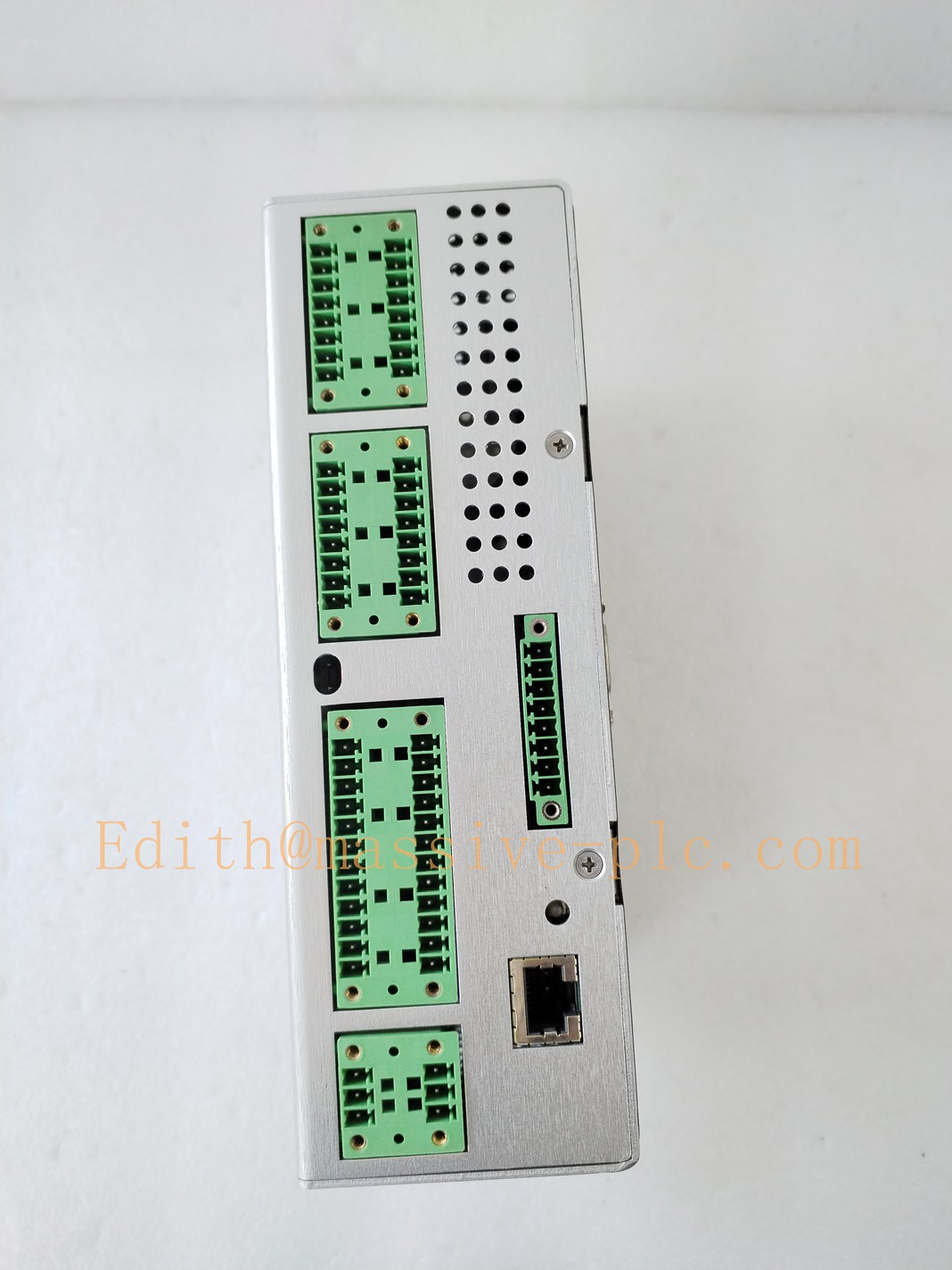
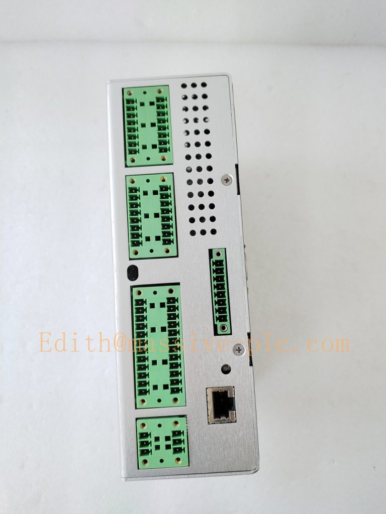
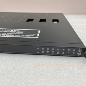
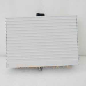
Stand‑alone panel‑mount metal housing. Rear side: large terminal blocks for sensor, power, relay, analog signal, Ethernet/RS485 port. Front side: optional LCD+keypad. Not hot‑swappable; power‑off before modifying field wiring.
Adaptive Quality Assurance & Test Protocol
3.1 Factory Adaptive QA Procedure
- Power‑on self‑diagnostic verification.
- Multi‑channel signal injection test: proximity / velocity / acceleration sensor simulation, verify measurement accuracy.
- Temperature channel simulation test for RTD & thermocouple.
- Alarm threshold & time‑delay test; relay logic combinatorial test (AND/OR voting).
- 4‑20 mA output linearity & isolation test.
- Buffered transducer output signal integrity test.
- Modbus communication function test (if fitted).
- Transducer fault simulation test (open‑circuit / short‑circuit).
- Environmental screening: temperature cycling, EMC noise‑immunity test.
- Serial‑number traceability, full functional‑test report archived.
3.2 On‑site Acceptance Test Protocol
- Visual inspection: Check housing, front‑panel display/keypad, rear‑side terminal blocks without damage or oxidation.
- Wiring check: Transducer sensors, temperature sensors, DC power supply, relay interlock wiring, 4‑20 mA to DCS, Modbus communication wiring.
- Power‑on test: Confirm OK status, self‑test completes without fault.
- Connect PC via USB port, use 1900 Configuration Software to set channel‑type, measurement range, Alert/Danger thresholds, relay logic, 4‑20 mA mapping.
- Inject simulated signal for each channel; verify local reading, alarm status, relay action, 4‑20 mA output value.
- Cross‑check DCS reading via 4‑20 mA or Modbus.
- Simulate sensor open/short fault, verify fault alarm trigger.
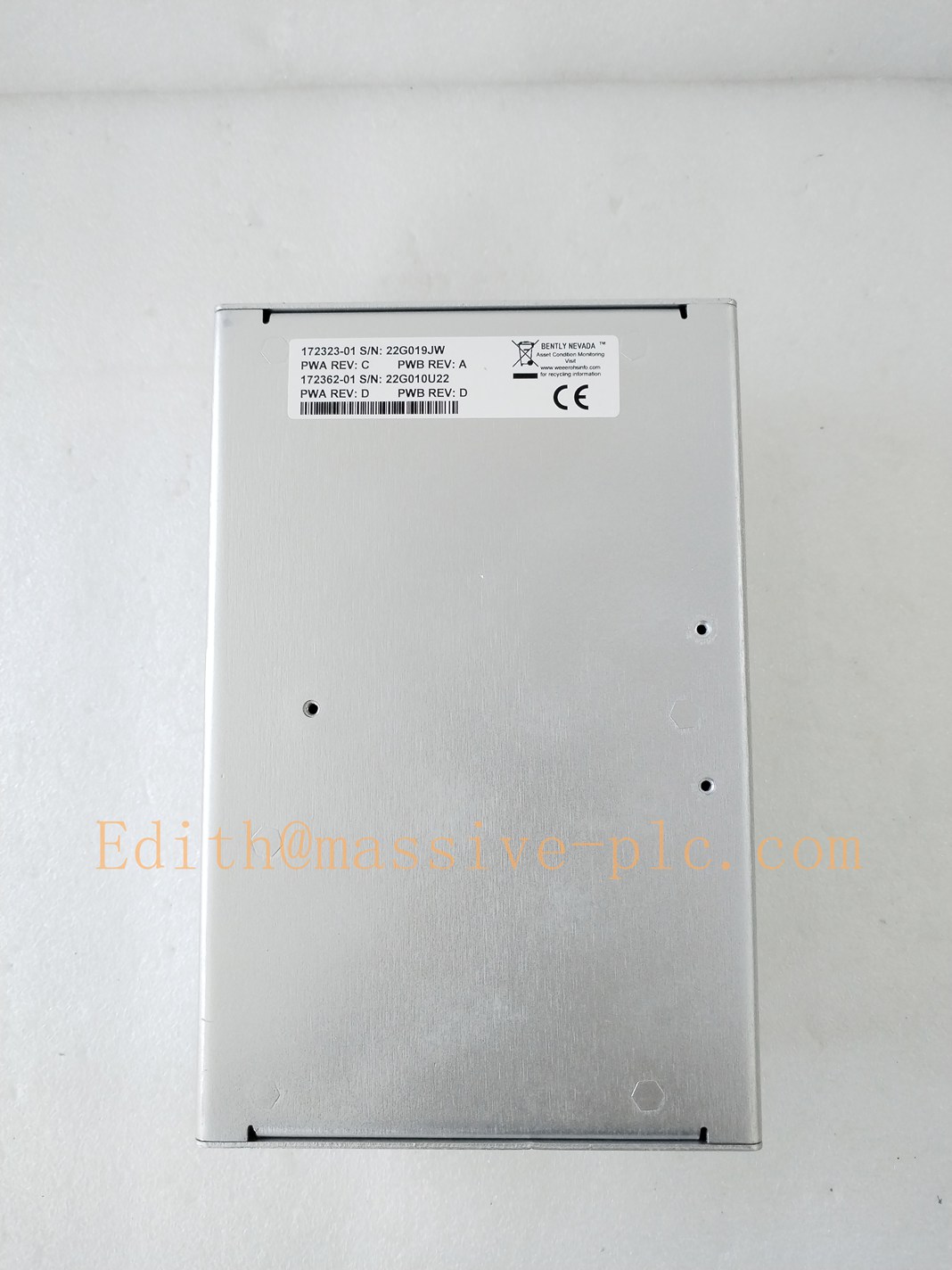
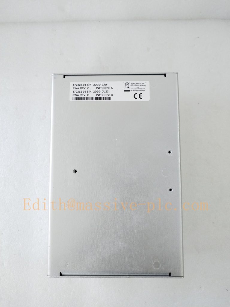
- Record part‑number, hardware‑revision, full order suffix code and test‑result snapshot for site QA archive.
190065A
Field Engineer Technical Notes
Installation Guidance
‑ Panel‑mount installation; maintain adequate rear‑side ventilation. ‑ Separate sensor cables from high‑voltage power cables to avoid EMI interference; use shielded cable with single‑end grounding. ‑ Confirm ordering suffix code before spare‑part purchase: distinguish units with / without LCD display, with / without Modbus gateway. Hardware options cannot be added on‑site without factory modification. ‑ Not a 3500 rack card; cannot install into 3500 rack chassis.
Field note: 1900/65A is legacy auxiliary‑monitor hardware. Many end‑users migrate to 2300‑series monitors for new‑project retrofits.
Commissioning Tips
‑ All configuration parameters are downloaded from PC 1900 Configuration Software; if unit without LCD, all setup must be done by USB‑PC connection. ‑ Set proper transducer fault alarm for sensor cable break protection. ‑ Cross‑validate: monitor reading shall be consistent with DCS/Modbus remote reading.
Troubleshooting Common Issues
- Unit no power: Check 9‑32 VDC power supply and rear‑terminal connection.
- Channel fault alarm: Inspect sensor and cable for open‑circuit / short‑circuit.
- Incorrect 4‑20 mA value: Re‑check software channel‑range configuration, loop load resistance and wiring.
- Modbus communication failure: Verify address, baud‑rate, parity and bus termination resistor.
Diagnostic: Read unit event log via 1900 Configuration Software for detailed fault codes.
Maintenance & Spare‑part Recommendation
‑ No field‑serviceable internal components; replace complete 1900/65A unit upon hardware failure. ‑ Spare‑part suggestion: Keep matched spare unit with identical ordering suffix (LCD / Modbus option consistent). ‑ Preventive inspection during shutdown: Check rear‑terminal tightening, cable shielding and aging.
190065A
1900‑series monitor comparison table
| Part Number | Channel config | Key feature | Display | Communication / Output |
|---|---|---|---|---|
| 1900/25 | 1‑ch velocity | Single‑channel velocity | Front LED display | Trendmaster‑Pro bus |
| 1900/27 | 1‑ch velocity | Single‑channel velocity | Front LED display | 4‑20 mA analog |
| 1900/55 | 4‑ch seismic | Fan‑optimized 4‑ch vibration | Front LCD | Trendmaster‑Pro / optional 4‑20 mA |
| 1900/65A | 4‑vib+4‑temp | Mixed‑sensor vibration+temperature | Optional front‑LCD | 4‑20 mA, 6 relays, optional Modbus RTU/TCP |


 Start Chat




