
Description
Bently Nevada 172103‑01 — 3500/65 RTD / Isolated‑Tip TC I/O Module (Internal Terminations)
Product Overview
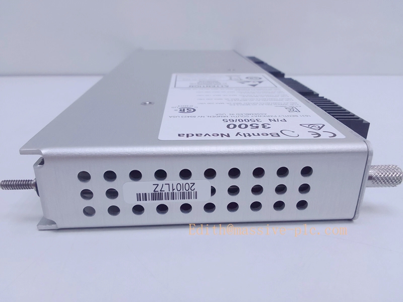
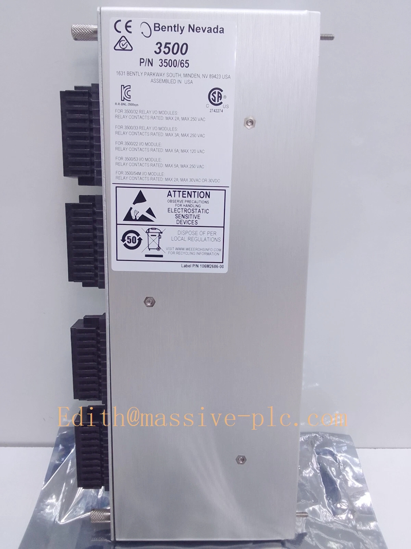
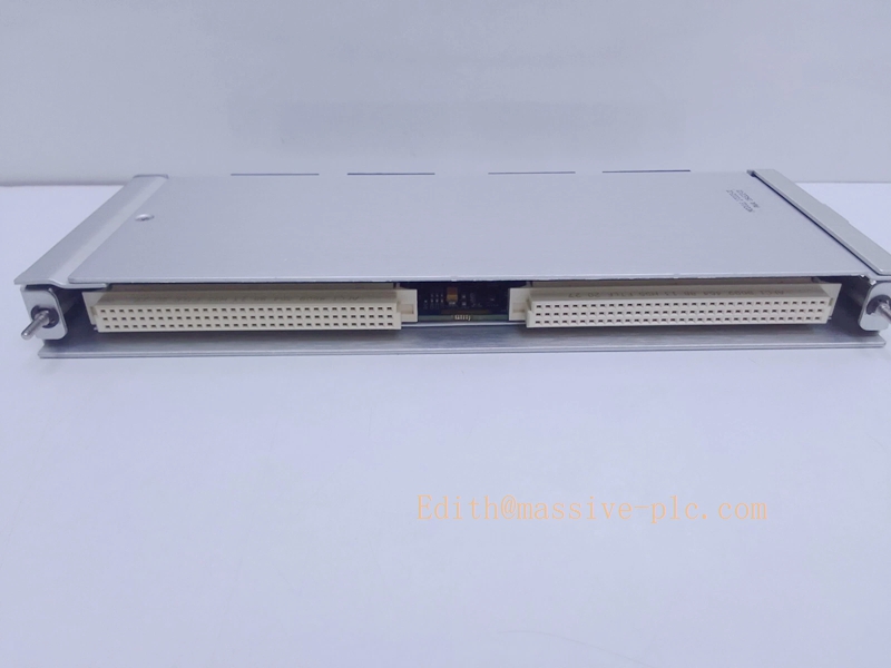
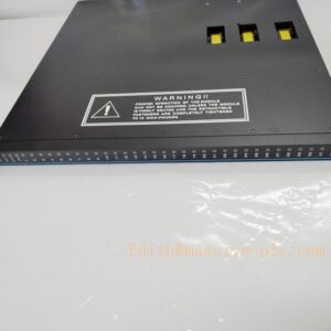
The 172103‑01 is the front‑panel I/O sub‑assembly for the 3500/65 16‑Channel Temperature Monitor, part of Bently Nevada 3500 machinery‑protection rack system. It features built‑in internal termination connectors, enabling direct field‑sensor wiring without external terminal blocks. It mates with main processor board 145988‑02 to form a complete 3500/65 monitor unit. This module accepts RTD and isolated‑tip thermocouple inputs, performs signal conditioning, channel diagnostics and communicates measured temperature data to the 3500 rack backplane for alarm evaluation and host‑system transmission.
Critical Compatibility Note
- Must pair with main board 145988‑02 to constitute full 3500/65 hardware.
- Only supports isolated‑tip thermocouples. Grounded‑tip thermocouples are prohibited and will introduce measurement error.
- Installs inside standard 3500 rack chassis, works with 3500 configuration software for channel parameter setup.
- Not compatible with 3300‑XL proximity probe / proximitor series.
172103‑01
Key Specifications
| Parameter | Value |
|---|---|
| Part Number | 172103‑01 |
| Module Family | 3500/65 Temperature Monitor Front‑Panel I/O Assembly |
| Input Channel Count | 16 channels, mixed‑sensor configurable |
| Supported Sensors | 3‑wire /4‑wire Pt100, Ni120, Cu10 RTD; Isolated‑tip TC: E, J, K, T, S, R, B types |
| RTD Measurement Range | ‑200 °C ~ +850 °C |
| Thermocouple Measurement Range | ‑200 °C ~ +1800 °C |
| Measurement Accuracy | ±0.1 % of reading ±1 digit |
| Termination Type | Internal integrated connectors (no external terminal block required) |
| Power Consumption | 3 W (shared with 145988‑02 main board) |
| Operating Temperature | ‑40 °C ~ +85 °C |
| Certifications | CE, ATEX, IECEx, CSA hazardous‑area approvals |
| Dimensions | 241.3 mm × 24.4 mm × 99.1 mm |
| Weight | ≈0.45 kg |
| Country of Origin | USA |
Main Features
- Internal termination design: Direct field‑sensor connection, eliminates external terminal block, reduces wiring complexity and potential fault points.
- 16 multi‑function channels: Each channel independently configurable for RTD or isolated‑tip thermocouple, mixed‑sensor mode supported within one module.
- Built‑in sensor fault detection: Detects open‑circuit, short‑circuit for every individual temperature channel.
- TMR triple‑modular‑redundant capable: Supports TMR voting architecture for high‑safety machinery‑protection applications.
- High noise‑immunity signal conditioning: Optimized for industrial cabinet EMI environment.
- Seamless integration with 3500 rack: Transmits temperature values and diagnostic status over rack backplane to system control module.
- Hazardous‑location qualified: Suitable for classified zones when deployed with approved barriers and correct installation practices.
- Robust industrial mechanical construction for continuous 24/7 turbomachinery operation.
Typical Application Scenarios
- Steam / gas turbine bearing metal temperature surveillance
- Refinery & petrochemical centrifugal compressor bearing, casing and lube‑oil temperature monitoring
- Gearbox, large critical pumps, blowers and motor‑winding temperature protection
- Power‑generation plant machinery‑protection rack systems
- Off‑shore platform rotating‑equipment condition‑monitoring cabinets
- Sites preferring internal termination without external terminal blocks
- Hazardous‑classified locations requiring ATEX / IECEx intrinsic‑safety compliance
- Spare‑part replacement for existing 3500/65 temperature monitor I/O front‑panel assemblies
Related & Recommended Alternative Models
| Model | Description |
|---|---|
| 145988‑02 | Main processor board for complete 3500/65 monitor (works together with 172103‑01) |
| 172104‑01 | 3500/65 I/O module with external terminal‑block interface (alternative version) |
| 3500/42M | Proximity / vibration monitor module for 3300‑XL proximity transducer system |
| 3500/22M | 3500 rack system‑control module |
| 3500/94 | Communication gateway for DCS / host‑system data interface |
Compatible Components & Accessories
- Matching main board: 145988‑02 PWA processor board (must assemble together with 172103‑01).
- 3500‑series rack infrastructure: Rack chassis, power supply, backplane, 3500/22M system‑control module.
- Field sensors: Pt100 / Ni120 / Cu10 RTD sensors; isolated‑tip‑only thermocouples.
- Configuration software: Official Bently Nevada 3500 rack configuration tool.
- Communication hardware: 3500/94 gateway for Modbus‑RTU data export to DCS.
- Hazardous‑area accessories: Approved intrinsic‑safety barriers, shielded sensor cables per ATEX/IECEx requirements.
Installation and Configuration Guide
Warning: Installation must be performed by qualified instrumentation technicians. Always refer to original Bently Nevada 3500‑series official manual as primary reference document.
- Mechanical Rack Assembly
- Power off 3500 rack power supply, apply anti‑static protection before handling module hardware.
- Physically combine 172103‑01 I/O front‑panel with 145988‑02 main processor board to build complete 3500/65 unit.
- Insert assembled monitor into available 3500 rack slot, latch securely to ensure solid backplane contact.
- For TMR redundant setup, occupy three adjacent rack slots as per project design.
- Field Sensor Wiring Rules
- Connect RTD and isolated‑tip thermocouple field cables directly onto 172103‑01 internal connectors.
- Strictly follow pin‑out diagram for 3‑wire /4‑wire RTD wiring and thermocouple polarity.
- Do not use grounded‑tip thermocouples, which will produce cross‑channel measurement error.
- Cable shield single‑point grounding: terminate shield only at rack chassis ground; avoid dual‑end grounding to prevent ground‑loop interference.
- Route low‑level temperature signal cables separately from high‑power AC, contactor and VFD cables to suppress EMI noise.
- Software Configuration Workflow
- Connect 3500 configuration software to rack communication port.
- Activate 3500/65 monitor module; configure each channel: select sensor type, set measurement range, program Alert / Danger alarm thresholds and alarm‑delay parameters.
- Download completed configuration to rack memory; verify module OK LED status, confirm no channel fault indications.
- Commissioning & Loop Validation
- Inject simulated temperature signal for each channel to verify reading accuracy.
- Simulate sensor open‑circuit and short‑circuit conditions to validate built‑in fault‑detection function.
- Confirm alarm events propagate to rack relay outputs or upper‑level DCS system.
- Maintenance & Troubleshooting
- Inspect module status LEDs during machinery turnaround. Loss of OK status indicates combined‑module hardware failure.
- Individual channel faults: check field sensors, cable integrity and internal connector contacts on 172103‑01.
- On‑site repair is not supported for 172103‑01; replace full assembled 3500/65 unit upon hardware damage.
- Hazardous‑Area Installation Notes
- For ATEX / IECEx classified‑zone deployment, strictly implement barrier specifications, shielded‑cable requirements and rack‑grounding rules defined in official manual.
Supplementary Remark
172103‑01 is the internal‑termination I/O front‑panel for 3500/65 sixteen‑channel temperature monitor, must be assembled with 145988‑02 main board for full functionality. It only accepts isolated‑tip thermocouples and multi‑type RTD inputs. Before commissioning, cross‑verify part number, hardware mating assembly, sensor type compatibility and rack‑slot assignment versus project BOM and mechanical drawings.


 Start Chat




