
Description
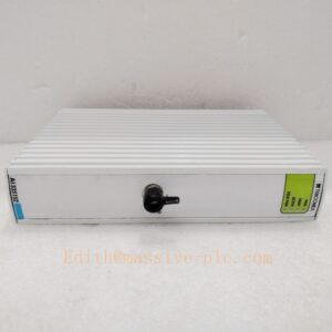
Bently Nevada 147663‑01 3500/22 TDI Transient Data Interface Module
Model Introduction
Model: 3500/22 TDI Transient Data Interface Module Part Number: 147663‑01 Device Type: Single‑slot front‑insert high‑speed transient data interface module for 3500 machinery protection rack Manufacturer: Bently Nevada (Baker Hughes) System Compatibility: Fits any user‑slot of full‑size 3500 rack. No dedicated rear‑I/O card. Works cooperatively with 3500/94M graphic display module, System 1 monitoring software, or external transient data collection host. Not compatible with mini‑rack. Application Scenarios: TSI turbine supervisory instrumentation, power‑plant steam turbines, gas turbines, compressors. Captures high‑speed transient waveform, keyphasor, orbit data for machine vibration analysis; provides high‑speed data path for 3500/94M VGA graphic‑display system. Complies with API‑670. Country of Origin: United States Lifecycle Status: Obsolete OEM discontinued; only aftermarket spare‑part available.
Important note: ‑ 3500/94M (184826‑01) cannot function without 3500/22 TDI 147663‑01. ‑ This is high‑speed transient data interface, NOT Modbus gateway. It does not output Modbus‑TCP / RTU to DCS. ‑ No rear‑I/O card; all high‑speed data interface signals locate on front‑panel edge connector.
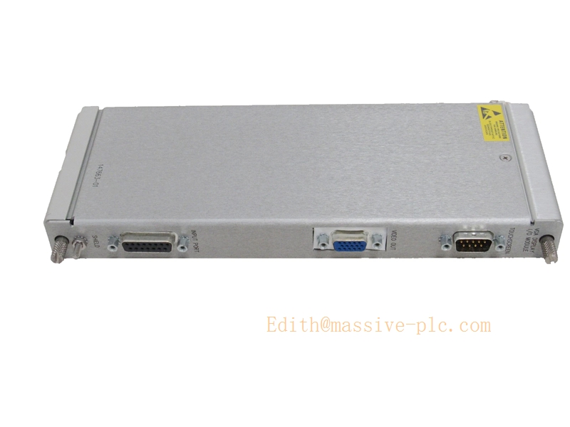
147663-01
Technical Introduction
Core Functions
‑ Acquire parallel high‑speed raw vibration waveform data from 3500 monitor modules via rack backplane. ‑ Output high‑speed transient data, orbit plots, Bode / polar plot data, keyphasor signals to external host or 3500/94M. ‑ Support event‑triggered waveform capture on alarm / trip condition. ‑ Interface for System 1 software high‑speed data acquisition. ‑ Provide mandatory high‑speed data bus for 3500/94M graphic‑display module. ‑ On‑board self‑diagnostics; report communication fault and hardware error into rack system event‑log.
Key Technical Specifications
| Item | Parameter |
|---|---|
| External Interface | High‑speed data port on front‑edge connector |
| Rack Bus | 3500 proprietary backplane bus |
| Waveform Sampling | Up to 200 kHz aggregate sampling rate |
| Power Supply | Powered fully by 3500 rack backplane 24 VDC |
| Power Consumption | 4.3 W typical |
| Operating Temperature | ‑30 ℃ ~ +65 ℃ |
| Storage Temperature | ‑40 ℃ ~ +85 ℃ |
| Humidity | 5 %‑95 % non‑condensing |
| Dimension | Standard single‑slot front‑insert module for full‑size 3500 rack |
| Weight | 0.41 kg |
| Compliance | API‑670, Class 1 Div 2 hazardous‑area certification, industrial EMC |
Mechanical Feature
Single‑slot hot‑swappable front‑insert module. No corresponding rear‑I/O card. High‑speed data connector is on front‑panel edge. Can be installed in any user‑slot. Hot‑swap supported under rack powered‑on condition; follow official maintenance procedure.
Adaptive Quality Assurance & Test Protocol
3.1 Factory Adaptive QA Procedure
- Backplane bus continuity test: Verify signal integrity between module connector and rack backplane, detect open‑circuit / short‑circuit defects.
- High‑speed waveform output test: Verify raw vibration waveform, keyphasor data transmission.
- Interoperability test: Pair with genuine 3500/94M (184826‑01), confirm graphic‑display high‑speed data path works normally.
- Alarm‑trigger waveform capture test: Simulate channel alarm, verify transient snapshot capture.
- Configuration download test: Download rack configuration via 3500 Rack Configuration Software.
- Fault‑simulation test: Simulate host communication loss; verify fault codes logged into rack event‑log.
- Environmental screening: Temperature cycling test, EMC noise‑immunity test.
- Built‑in self‑diagnostic execution; serial‑number traceability, full functional‑test report archived.
3.2 On‑site Acceptance Test Protocol
- Visual inspection: Check module physical integrity, front‑edge connector pins without damage or oxidation.
- Rack installation test: Insert 147663‑01 into any user‑slot of full‑size 3500 rack; power‑on, connect via configuration software, confirm no hardware mismatch alarms.
- Data‑path test: If 3500/94M is present, verify graphic‑display loads waveform/orbit data normally.
- Waveform capture test: Trigger manual capture, confirm raw vibration waveform and keyphasor data available in System 1 or display interface.
- Alarm‑trigger test: Force channel alert/danger condition, verify automatic transient snapshot capture.
- Communication‑break simulation: Disconnect/reconnect high‑speed host cable; verify fault reporting and auto‑recovery.
- Test‑record filing: Log part‑number, hardware revision, firmware version, test‑result snapshot for site QA archive.
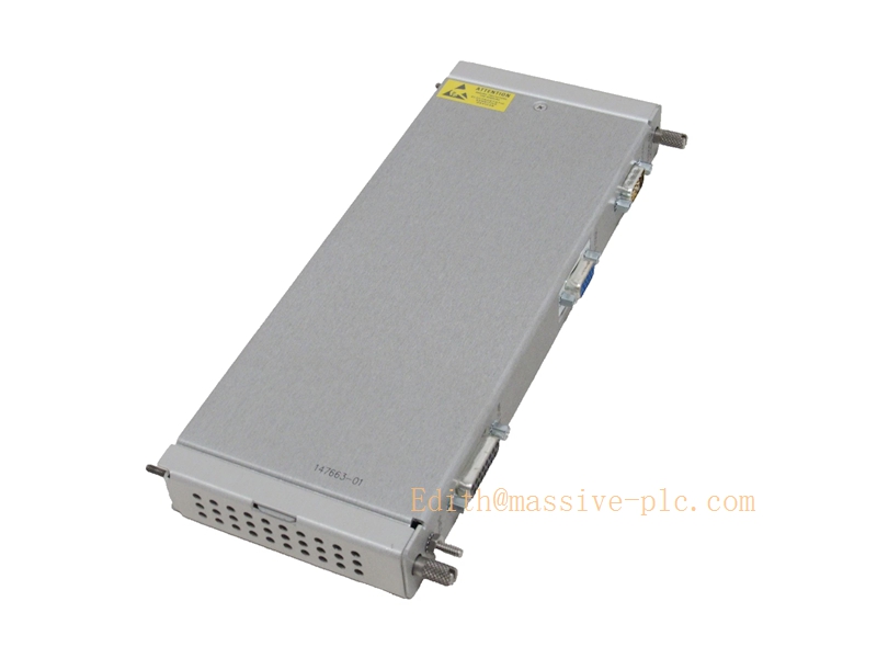
147663-01
Field Engineer Technical Notes
Installation Guidance
‑ Slot rule: 147663‑01 (3500/22 TDI) can be installed in any user‑slot of full‑size 3500 rack; no dedicated slot requirement. Not compatible with mini‑rack. ‑ No rear‑I/O card. High‑speed data wiring connects to front‑module edge connector. ‑ When using 3500/94M graphic‑display, 3500/22 TDI must exist inside rack, otherwise 3500/94M cannot obtain high‑speed waveform data. ‑ Important distinction: 3500/22 TDI is for high‑speed waveform / orbit data; it does NOT provide Modbus output to DCS/PLC. For Modbus, deploy 3500/91 /91M /92 gateway.
Field note: 147663‑01 is obsolete legacy hardware, aftermarket‑only inventory. Many sites retire 3500/94M + 3500/22 hardware and migrate to System 1 PC‑based acquisition solution.
Commissioning Tips
‑ After 3500/22 installation, download complete rack configuration. Enable transient‑data capture function inside software. ‑ If paired with 3500/94M, confirm TDI is detected by rack configuration software before configuring graphic‑display pages. ‑ Cross‑validate: waveform, orbit and keyphasor data should be consistent between host software and rack.
Troubleshooting Common Issues
- Module not recognized: Reseat module firmly; inspect backplane connector for dirt or oxidation.
- No waveform/orbit data on 3500/94M: Confirm 147663‑01 TDI present and without fault; re‑download rack configuration.
- Intermittent transient‑data dropout: Check front‑edge connector tightness, high‑speed cable shielding and grounding; eliminate ground‑loop interference.
Diagnostic reference: Read rack system event‑log inside 3500 Rack Configuration Software for 3500/22 fault codes.
Maintenance & Spare‑part Recommendation
‑ No user‑serviceable components onboard; replace complete 147663‑01 module upon hardware failure. ‑ Spare‑part suggestion: Keep spare 147663‑01 for legacy racks equipped with 3500/94M graphic‑display. If 3500/94M is decommissioned, TDI may also be removed. ‑ Preventive inspection during shutdown: Check front‑edge connector tightness, cable aging and shielding integrity.
Related‑module matching reference table
| Part Number | Module Type | Rear‑I/O Card | Critical dependency | Main function |
|---|---|---|---|---|
| 147663‑01 | 3500/22 TDI Transient Data Interface | None | Mandatory for 3500/94M | High‑speed waveform/orbit/keyphasor data output |
| 184826‑01 | 3500/94M VGA graphic‑display main module | 190214‑01/02 | Requires 3500/22 TDI | Local VGA graphic HMI + VNC |


 Start Chat




