
Description
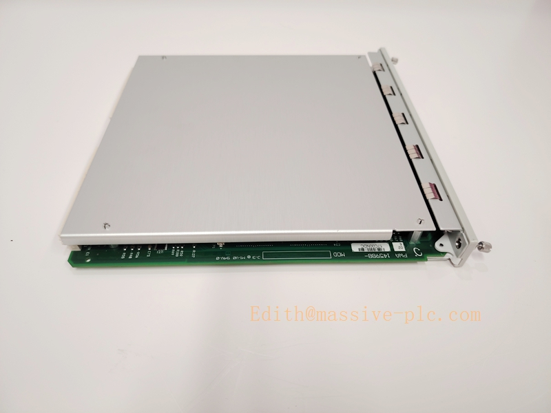
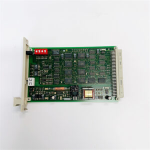
Bently Nevada 145988‑02 — 3500/65 16‑Channel Temperature Monitor
Product Overview
The 145988‑02 is the circuit board assembly for Bently Nevada 3500/65 Temperature Monitor module, belongs to 3500 machinery protection rack system. It provides 16 independent temperature input channels for critical rotating equipment, supporting both RTD and isolated‑tip thermocouple signals. It converts sensor inputs into digital values, supports user‑configurable Alert / Danger alarm thresholds, communicates with 3500 rack system and host configuration software. Widely used on turbines, compressors, pumps in power, refinery and petrochemical plants.
Important Compatibility Note
- Must install inside standard Bently 3500 series rack chassis.
- Works with 3500 rack configuration software for channel setup, alarm parameters and diagnostic viewing.
- Not a proximity transducer module; independent from 3300‑XL probe / proximitor series.
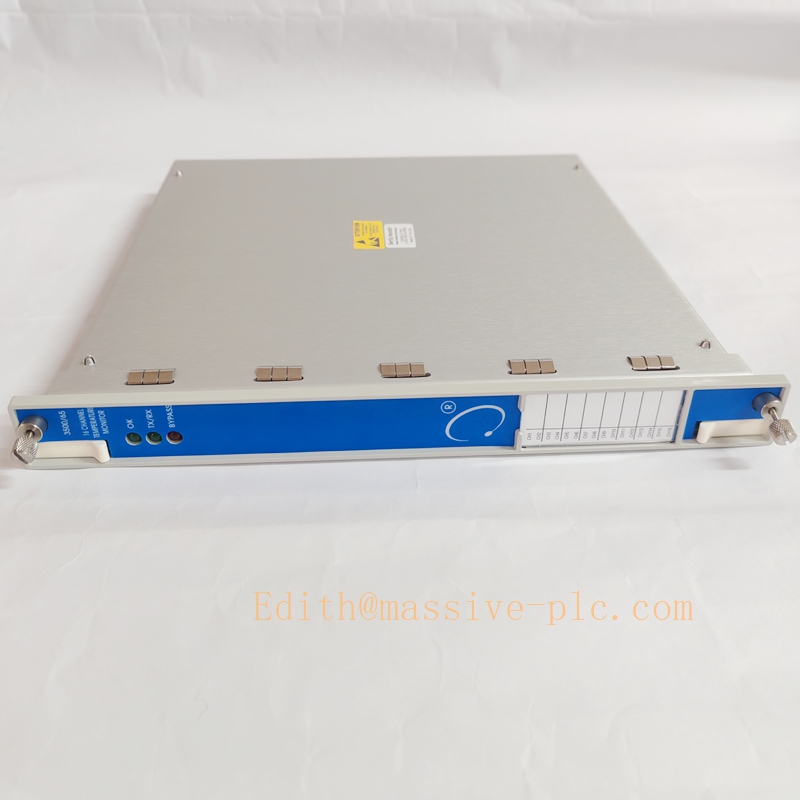
350065 145988-02
Key Specifications
| Parameter | Value |
|---|---|
| Part Number | 145988‑02 (PWA board for 3500/65‑01‑00) |
| Module Designation | 3500/65 16‑Channel Temperature Monitor |
| Channel Count | 16 isolated input channels |
| Supported Sensor Types | 3‑wire /4‑wire 100Ω Platinum RTD; Isolated‑tip TC: E, J, K, T type thermocouples |
| RTD Measurement Range | ‑200 °C ~ +800 °C |
| Thermocouple Measurement Range | ‑200 °C ~ +1800 °C |
| Accuracy | ±0.1 % reading ±1 digit |
| Power Consumption | 3 Watts |
| Input Impedance | >1 MΩ |
| Front‑panel LED | OK, TX/RX, Bypass indicator |
| Operating Temperature | ‑40 °C ~ +85 °C |
| Certifications | CE, ATEX, IECEx intrinsic‑safety approvals |
| Country of Origin | USA |
| Weight | ≈0.75 kg |
Main Features
- 16 multi‑mode temperature input channels, mixed RTD / thermocouple configuration available per channel.
- Two‑stage hardware alarm: Alert and Danger, programmable threshold & alarm delay.
- Built‑in sensor break / short‑circuit detection for each channel.
- Fully integrated within 3500 rack framework; TMR triple‑modular‑redundant capable for high‑safety application.
- Diagnostics readable via 3500 configuration software.
- Suitable for hazardous area when deployed with approved rack and barrier setup.
- Designed for continuous long‑term operation on critical turbomachinery.
Typical Application Scenarios
- Steam / gas turbine bearing metal temperature monitoring
- Refinery & petrochemical centrifugal compressor bearing & casing temperature surveillance
- Large critical pumps, blowers and gearbox temperature protection
- Power generation plant machinery protection systems
- Off‑shore platform rotating‑machinery condition‑monitoring racks
- Hazardous classified locations requiring ATEX / IECEx certification
- Spare‑part replacement for existing 3500/65 temperature monitor channels
Related & Recommended Alternative Models
| Model | Description |
|---|---|
| 145988‑01 | Earlier revision PWA board for 3500/65 module |
| 3500/42M | Proximity / vibration monitor module for 3300‑XL probe system |
| 3500/22M | System control module for 3500 rack |
| 3500/94 | Rack communication gateway module |
Compatible Components & Accessories
- 3500‑series rack chassis: 3500 rack power supply, backplane, system control module 3500/22M.
- Sensors: 100Ω Pt RTD; isolated‑tip type E/J/K/T thermocouples.
- Configuration tool: Bently 3500 rack configuration software.
- System communication: 3500/94 for host / DCS Modbus‑RTU connection.
- Hazardous‑area accessories: Approved safety barriers and field wiring per ATEX/IECEx requirement.
Installation and Configuration Guide
Warning: Installation shall be performed by qualified instrumentation technicians. Always refer to original Bently Nevada 3500 series official manual as primary reference document.
- Rack Installation
- Insert 3500/65 module (145988‑02 board assembly) into available slot of 3500 rack, secure module latch.
- Ensure rack backplane, power supply and system control module 3500/22M are functional.
- Observe cabinet operating temperature limits ‑40 °C ~ +85 °C, avoid excessive heat and condensation.
- Field Sensor Wiring
- Route RTD / thermocouple field cables, separate from high‑power AC cables to minimize EMI noise.
- Strictly follow terminal diagram for 3‑wire /4‑wire RTD and thermocouple polarity.
- For hazardous installation, apply required intrinsic‑safety barriers and cable specifications.
- Software Configuration
- Connect 3500 configuration software to rack communication port.
- Activate 3500/65 module, for each channel select sensor type (RTD / TC type), set measurement range, Alert & Danger alarm thresholds and alarm delay.
- Download configuration to rack, verify OK LED status, confirm no channel fault indication.
- Commissioning & Loop Check
- Inject simulated temperature signal for each channel to verify reading accuracy and alarm trigger.
- Simulate sensor open‑circuit / short‑circuit to confirm fault detection function works.
- Confirm alarm events can be passed to rack relay outputs or upper‑level DCS system.
- Maintenance & Troubleshooting
- Check module status LED during unit turnaround; OK light off indicates module hardware fault.
- Individual channel fault: inspect field sensor, wiring, terminal connection.
- Module hardware failure: replace complete 3500/65 module assembly; 145988‑02 board is not field‑repairable component.
Supplementary Remark
145988‑02 is the printed‑wiring‑assembly board for 3500/65‑01‑00 sixteen‑channel temperature monitor, belongs to Bently 3500 machinery protection rack system, for RTD and isolated‑tip thermocouple temperature monitoring. It is not part of 3300‑XL proximity transducer family. Before commissioning, cross‑check part revision, rack compatibility and sensor wiring against project BOM and official manual.


 Start Chat




