

Description
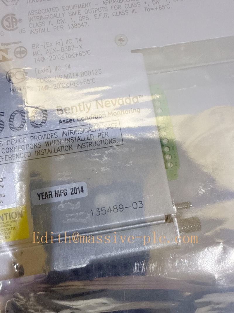
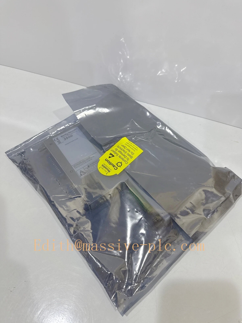
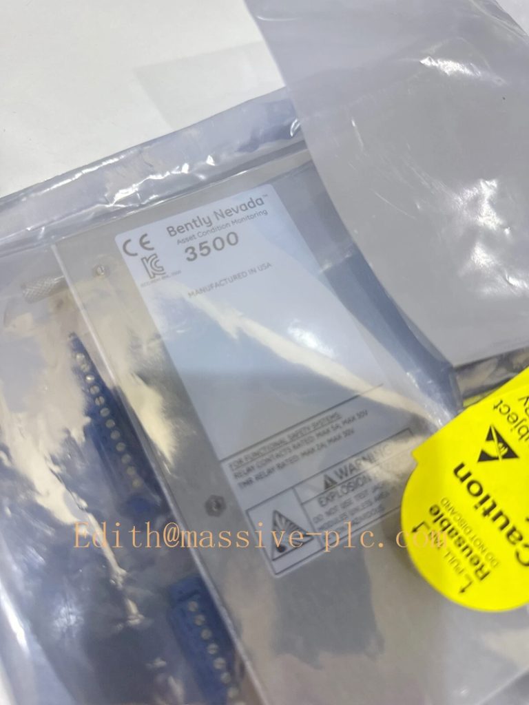
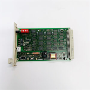
Bently Nevada 135489‑03 Internal‑Barrier Internal‑Termination I/O Assembly
Product Overview
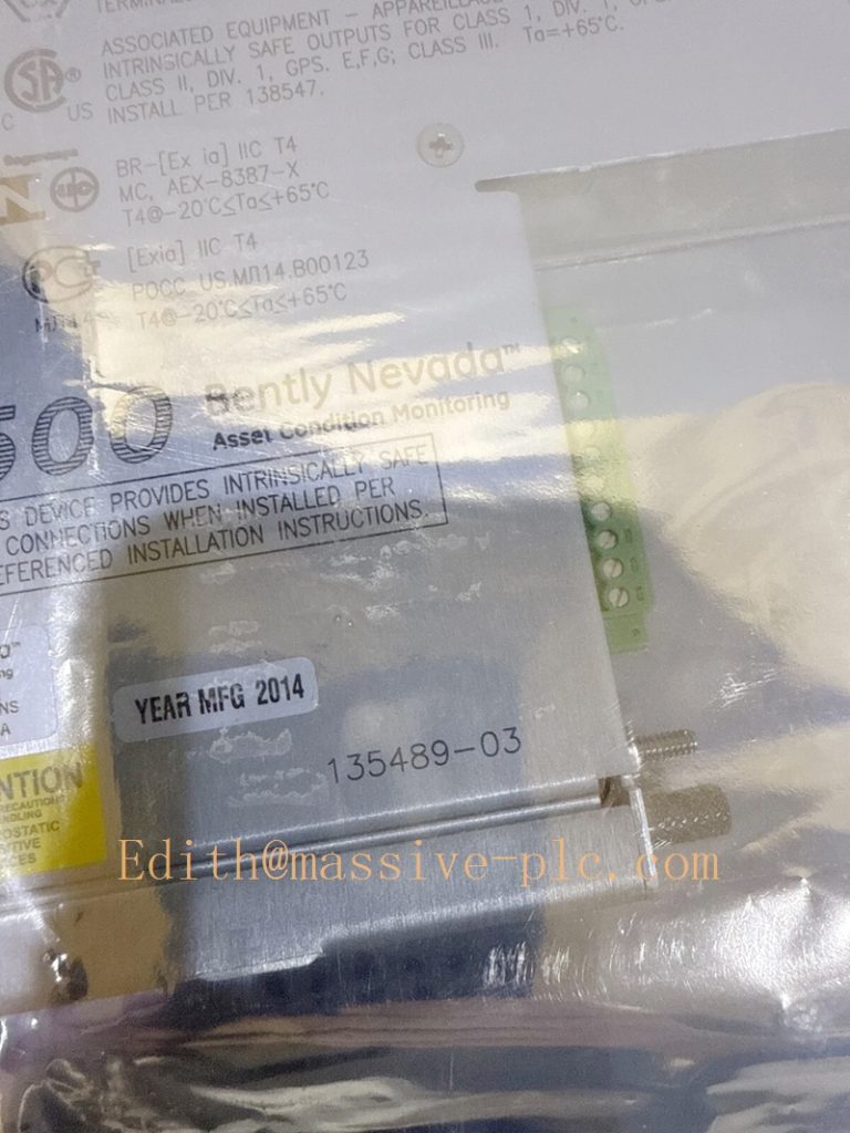
135489‑03 is internal‑termination I/O assembly with built‑in intrinsic‑safety barriers exclusively for 3500/70M Recip Impulse Velocity Monitor (176449‑09) of Bently Nevada 3500 machinery‑protection systemBaker Hugh…. It provides rear‑rack wiring terminals for accelerometers and seismic transducers mounted in ATEX / Class I Div 2 hazardous classified zones. Built‑in IS barriers offer explosion protection for field sensor circuits, transmitting impulse‑vibration signals to the 3500/70M main monitor via rack backplane connector. Cannot operate independently; must install behind 176449‑09 in same rack slot.
Important note: Do NOT interchange with 135489‑01 / 135489‑02 (these two are for 3500/42M rotating‑machinery monitor). Even similar part‑number series, hardware is incompatible。
135489-03
Technical Specifications
| Item | Parameter |
|---|---|
| Part Number | 135489‑03 |
| Matching Main Board | 3500/70M (176449‑09) Recip Impulse Velocity Monitor |
| Termination Style | Internal Termination with integrated intrinsic‑safety barrier |
| Input Channels | 4 independent channels (pair‑wise configuration Ch1‑2 / Ch3‑4) |
| Supported Sensors | Accelerometers, seismic velocity transducers for reciprocating compressors |
| Hazardous‑Area Compliance | ATEX / FM / CSA intrinsic‑safety approval for Class I Div 2 / Zone2 field instruments |
| Power Supply | Powered from 3500 rack backplane bus |
| Typical Power Consumption | 1.8 W |
| Operating Temperature | ‑30 ℃ ~ +65 ℃ (rack); Storage:‑40 ℃ ~ +85 ℃ |
| Form Factor | Single‑slot plug‑in for standard 3500 instrument rack |
| Weight | Approx. 0.46 kg |
| Compliance | API 618, API 670; supports hot‑swap function |
| Installation | Installed directly behind 176449‑09 main monitor in identical rack slot |
Key Features
- Built‑in intrinsic‑safety barrier: Eliminates external barrier modules. Directly connect IS‑certified accelerometers / seismic sensors installed in explosive hazardous zones for reciprocating‑compressor projects.
- Internal termination design: Field sensor cables land directly on rear‑rack screw terminals; no intermediate jumper cables required, simplifies cabinet layout.
- Four‑channel pair‑wise measurement: Channels work in pairs (1‑2,3‑4) for impulse‑acceleration, reciprocating velocity measurement for cross‑head impact and frame vibration of reciprocating compressors.
- Full transducer‑loop supervision: Enables 3500/70M main board to detect sensor open‑circuit, short‑circuit and cable‑loop fault diagnostics.
- Configuration‑transparent hardware: No separate software setup. Measurement modes, alarm thresholds and filter parameters are set in 3500 Rack Configuration Software for paired 3500/70M monitor.
- Hot‑swap capable: Supports online replacement following Bently official maintenance procedure.
Family comparison of 135489 series IS‑barrier I/O
表格
| Part Number | Target Main Monitor | Channel hardware assignment | Application scenario |
|---|---|---|---|
| 135489‑01 | 3500/42M | 4‑ch Proximity / Accelerometer | Rotating machine hazardous‑area, all displacement inputs |
| 135489‑02 | 3500/42M | 2×Prox/Accel + 2×Velomitor fixed | Rotating machine hazardous‑area, mixed displacement+velocity |
| 135489‑03 | 3500/70M | 4‑ch Accelerometer / Seismic (reciprocating compressor only) | Reciprocating‑compressor hazardous‑area impulse‑vibration monitoring |
| 140734‑09 | 3500/70M | 4‑ch Accelerometer / Seismic non‑barrier | Reciprocating‑compressor safe‑area installation |
Typical Applications & Application Scenarios
Main Applications
- Intrinsically‑safe signal interface for accelerometers and seismic transducers paired with 3500/70M reciprocating impulse velocity monitor.
- Capture cross‑head impact signal, crankcase frame vibration of reciprocating compressors.
- Detect cross‑head pin wear, connecting‑rod looseness, valve failure, packing abnormal conditions.
- Provide impulse‑vibration waveform for Alert/Danger alarm, machinery‑protection trip interlock and predictive‑maintenance trending for System 1 / DCS / SCADA.
Industry Scenarios
- Oil & gas: offshore platforms, refineries, natural‑gas reciprocating‑compressor stations with ATEX / Class I Div 2 hazardous classified zones.
- Petrochemical plants: hydrogen compressors, hyper‑compressors and process‑gas reciprocating compressors complying with API 618 standard.
135489-03
Supporting / Matching Components
- Mandatory paired main monitor: 176449‑09 (3500/70M) Recip Impulse Velocity Monitor; standalone operation prohibited.
- Host rack: 3500/05 instrument rack.
- Rack power supply: 3500/15 series power‑supply modules.
- Field sensors: IS‑certified accelerometers / seismic transducers and intrinsically‑safe shielded field cables for reciprocating compressors.
- Auxiliary modules:
- 3500/32M / 3500/33 relay modules for hardware alarm & trip contact output
- 3500/92 / 3500/77M gateway modules for uploading vibration data and alarms
- Configuration software: Bently Nevada 3500 Rack Configuration Software.
Related & Reference Part Numbers
- 176449‑09: 3500/70M main monitor board
- 140734‑09: Non‑barrier internal‑termination I/O for 3500/70M (safe‑area)
- 3500/70M‑01‑02: Complete assembly (176449‑09 +135489‑03 internal‑IS‑barrier I/O)
- 135489‑01 / 135489‑02: IS‑barrier I/O for 3500/42M rotating‑machine monitor (non‑interchangeable with 3500/70M)
- 3500/72M: Recip Rod‑Position / Rod‑Drop monitor (reciprocating‑compressor companion monitor)
- 3500/77M: Recip Cylinder‑Pressure monitor (P‑V‑curve diagnosis)
135489-03
Installation & Maintenance Notes
- 135489‑03 must install behind 176449‑09 in same rack slot. Cannot mix‑use barrier‑type and non‑barrier‑type I/O for a single 3500/70M monitor set.
- Only connect intrinsically‑safe certified sensors and cables, strictly comply with local hazardous‑area installation standards.
- Separate IS signal wiring from high‑voltage non‑IS cables to avoid noise interference.
- After installation, validate channel health status, sensor fault‑detection and alarm logic inside 3500 configuration software.
- Execute hot‑swap replacement strictly following Bently Nevada official service manual.

 Start Chat




