
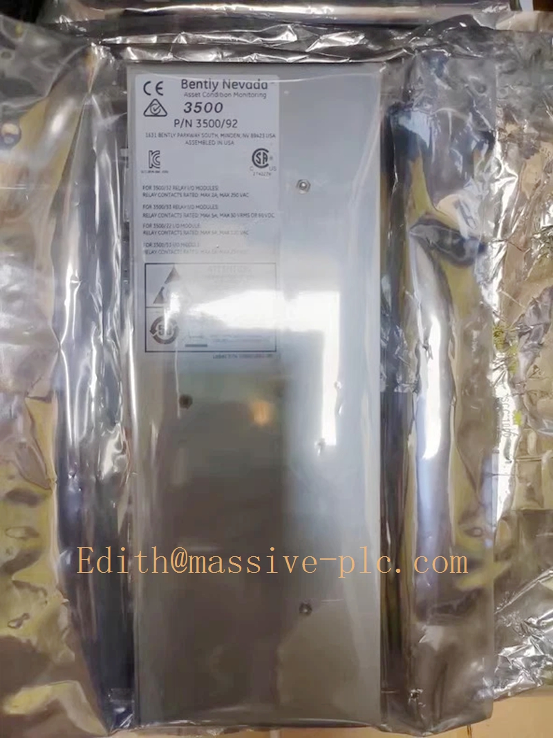
Description
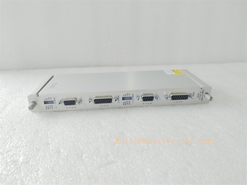
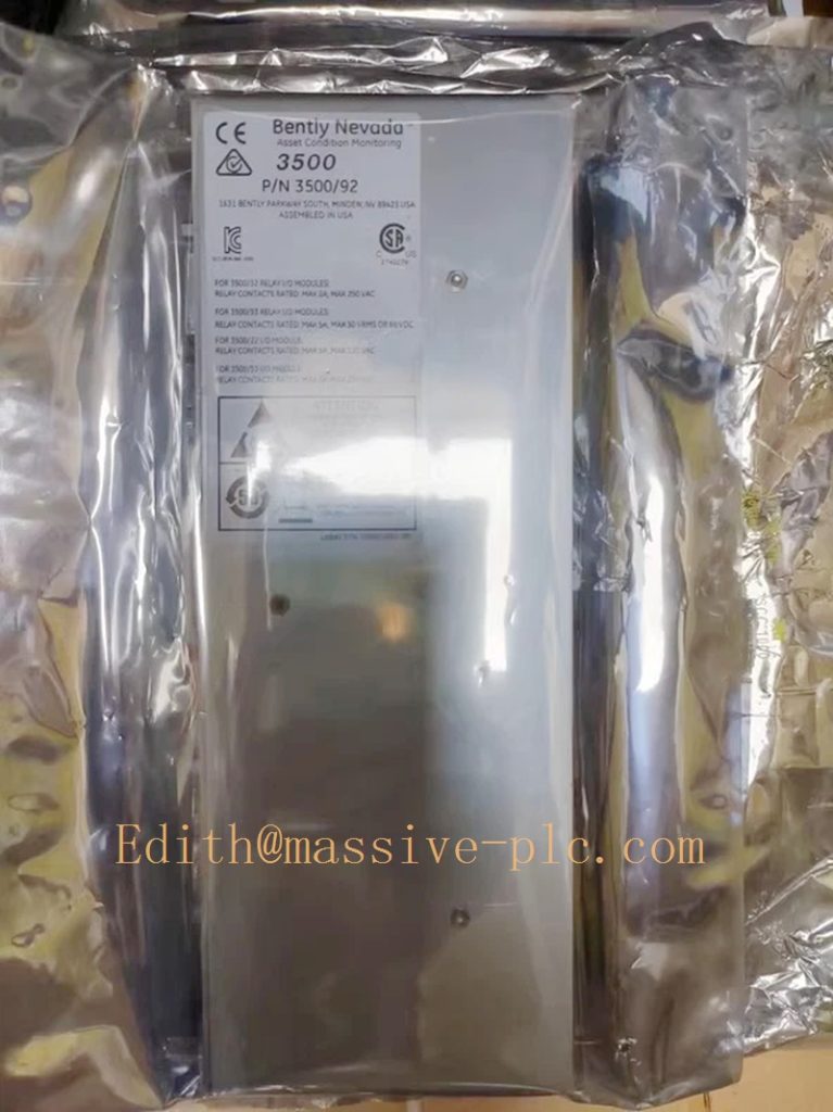
Bently Nevada 133323‑01 Rear I/O Card for Early‑Version 3500/92
Model Introduction
Model: Modbus RS485 Rear I/O Card for 3500/92 Part Number: 133323‑01 Device Type: Full‑height rear‑mount communication termination I/O card, early‑generation rear hardware for 3500/92 gateway Manufacturer: Bently Nevada (Baker Hughes) System Compatibility: Exclusively mates with early front‑module 125736‑01 (3500/92 original front‑side gateway). Cannot pair with later updated front modules 136180‑01 nor later rear‑cards 136188‑01 / 136188‑02. Standalone operation is not allowed. Application Scenarios: TSI turbine supervisory instrumentation, thermal‑power steam turbines, oil‑gas centrifugal compressors, legacy rotating‑machinery protection racks. Provides physical field‑wiring termination for multi‑mode serial ports and Ethernet interface, bridges 3500 rack backplane bus to external DCS, PLC, SCADA and plant historian systems. Country of Origin: United States Lifecycle Status: Obsolete legacy rear‑card, OEM manufacturing discontinued; only aftermarket spare‑part support available. Recommended full set replacement: 136180‑01 + 136188‑02.
Note: 133323‑01 is the original first‑generation rear I/O for 3500/92 (matched to front 125736‑01). Later hardware revision redesign replaced this assembly with 136188‑01 / 136188‑02 series, which work with updated front‑module 136180‑01. No cross‑compatibility between 133323‑01 and 136188‑xx hardware families.
133323-01
Technical Introduction
Core Functions
‑ Provides physical termination for 10/100BASE‑TX Ethernet RJ45 port for Modbus‑TCP and Bently Nevada proprietary configuration protocol. ‑ Multi‑mode serial terminal block supporting RS232 / RS422 / RS485 for Modbus‑RTU communication. ‑ Routes backplane bus signals from 125736‑01 front gateway module out to field communication cables. ‑ Basic port isolation and transient‑voltage suppression for industrial noise mitigation. ‑ All field‑side wiring terminates on this rear‑I/O card; front‑side 125736‑01 completes protocol processing and configurable Modbus register mapping.
Key Technical Specifications
| Item | Parameter |
|---|---|
| Ethernet Interface | 10BASE‑T /100BASE‑TX, auto‑negotiation, RJ45 connector |
| Serial Interface | RS232 / RS422 / RS485, Euro‑style plug‑in screw terminals |
| Rack Bus Interface | 3500 proprietary backplane mating connector (early‑generation pin assignment) |
| Power Supply | Supplied fully by 3500 rack backplane 24 VDC |
| Operating Temperature | ‑30 ℃ ~ +65 ℃ |
| Storage Temperature | ‑40 ℃ ~ +85 ℃ |
| Humidity | 5 %‑95 % non‑condensing |
| Dimension | 241.3 mm × 24.4 mm × 99.1 mm |
| Weight | 0.40 kg |
| Compliance | API 670 compliant under complete valid rack configuration; industrial EMC certification |
Mechanical Feature
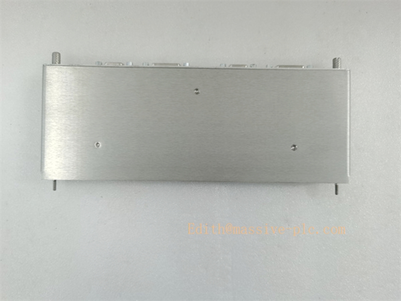
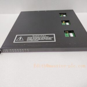
Full‑height rear‑slot I/O card installed behind the 3500 rack backplane, mates one‑to‑one with early‑release front‑inserted 125736‑01 3500/92 main module. Hot‑swap supported under rack powered‑on state; strictly follow official maintenance procedure during replacement. Early‑generation backplane pin‑out is not compatible with 136188‑xx mechanical successors.
133323-01
Adaptive Quality Assurance & Test Protocol
3.1 Factory Adaptive QA Procedure
- Backplane continuity test: Verify pin‑to‑pin signal integrity between rear‑card connector and mating interface for 125736‑01 front module; detect open‑circuit / short‑circuit defects.
- Ethernet physical‑layer adaptive test: Validate 10 Mbps /100 Mbps full‑duplex / half‑duplex auto‑negotiation; repeated link‑up / link‑down stress cycling.
- Serial‑port adaptive validation: RS232 / RS422 / RS485 mode‑switching test; multi‑baud‑rate stress test.
- Protocol interoperability test: Pair with genuine 125736‑01 front module; execute Modbus‑TCP register read‑write, Modbus‑RTU master‑slave transaction, Bently proprietary protocol connection test under rack simulation environment.
- EMC surge‑immunity screening: Basic surge test for communication ports (note: early‑generation protection circuit, lower surge margin versus later 136188‑02 hardware).
- Mismatch‑detection validation: Confirm rack triggers hardware‑mismatch alarm when paired with non‑125736‑01 front gateway modules.
- Visual & label inspection: Serial‑number traceability, part‑number marking verification; full functional‑test report archived.
3.2 On‑site Acceptance Test Protocol
- Visual inspection: Check card physical condition, connector pin integrity, no oxidation or mechanical damage.
- Rack mating test: Install 133323‑01 rear‑I/O card together with matched 125736‑01 front module; power‑on rack, connect with 3500 Rack Configuration Software, confirm no rear‑card mismatch alarms.
- Ethernet link test: Connect industrial shielded Ethernet cable; verify link LED status; establish Modbus‑TCP connection and read measurement & alarm registers.
- Serial‑port function test: Wire serial terminals, configure baud‑rate, parity and stop‑bit; validate Modbus‑RTU read‑write transactions.
- Self‑diagnostic test: Trigger module self‑test from configuration software; confirm zero critical faults in rack system event‑log.
- Communication‑recovery simulation: Simulate cable disconnection and reconnection for Ethernet and serial channels; verify automatic communication recovery without rack disturbance.
- Test‑record filing: Log part‑number, hardware revision, firmware version, test‑result snapshot for site QA archive.
Field Engineer Technical Notes
Installation Guidance
‑ Strict pairing rule: 133323‑01 rear‑I/O card must work exclusively with front‑side 125736‑01. It cannot be used with 136180‑01 front module or 136188‑01/02 rear‑cards due to backplane pin‑out incompatibility. Mismatched hardware will trigger fatal hardware‑mismatch alarm and total communication failure. ‑ Mount on rack rear‑side; align backplane connector firmly; tighten retaining screws to avoid intermittent poor‑contact faults. ‑ Ethernet wiring: Use industrial‑grade shielded CAT5e / CAT6 cable; implement single‑end shield grounding per plant drawing, avoid multi‑point ground‑loops. ‑ Serial wiring: RS422 / RS485 adopt shielded twisted‑pair cable; terminate bus end‑resistor as required for multi‑drop bus topology. ‑ No external power connection to rear‑card; power is supplied entirely from rack backplane.
Field note: Since 133323‑01 is obsolete early‑revision hardware, spare‑part supply is limited. For existing racks with 125736‑01 + 133323‑01, full upgrade set (136180‑01 + 136188‑02) is recommended for turnaround maintenance.
Commissioning Tips
‑ After hardware installation, download complete rack configuration; activate 3500/92 gateway function in slot‑configuration table. ‑ Assign static IP address for Ethernet port; avoid IP conflict within plant LAN. ‑ Match serial‑port parameters (baud‑rate, parity, stop‑bit, slave ID) strictly with upper‑level DCS / PLC settings. ‑ Apply Configurable Modbus Register Utility to define required measurement points and alarm bits before downloading configuration. ‑ Cross‑validate data consistency between rack local readings and DCS receiving values.
Troubleshooting Common Issues
- Module Mismatch Alarm: Confirm front‑module is genuine 125736‑01; cross‑check rear‑card part‑number. Hardware cannot be substituted with 136188‑xx series.
- Ethernet link‑down: Inspect RJ45 connector, cable integrity, switch‑port status and IP subnet matching.
- Serial‑port communication unstable: Early‑generation hardware has lower surge‑immunity; check wiring polarity, bus terminal‑resistor setting; verify serial‑parameter consistency at both sides.
- Missing / abnormal Modbus register data: Recheck Modbus register mapping configuration; re‑download rack configuration.
- Intermittent data dropout: Check cable shielding & grounding, eliminate ground‑loop interference.
Diagnostic reference: Read rack system event‑log in 3500 configuration software for root‑cause analysis.
Maintenance & Spare‑part Recommendation
‑ No user‑serviceable components onboard; replace full rear‑card assembly upon hardware failure. ‑ Spare‑part suggestion: For legacy racks running 125736‑01 + 133323‑01, prepare full upgrade spare set 136180‑01 + 136188‑02 as drop‑in replacement solution. ‑ Preventive inspection during unit shutdown: Check rear‑card mounting tightness, terminal‑screw torque, connector oxidation, cable aging and shielding integrity.
133323-01
3500/92 Gateway Hardware‑Revision Full Comparison Table
| Front‑Module Part No. | Matched Rear‑I/O Part No. | Module Description |
|---|---|---|
| 125736‑01 | 133323‑01 | 3500/92 Original Early‑Version Set (Obsolete, unique backplane pin‑out) |
| 125736‑01 | 136188‑01 / 136188‑02 | ❌ Not compatible |
| 136180‑01 | 136188‑01 | 3500/92 Updated Multi‑Protocol Gateway (original rear‑card revision) |
| 136180‑01 | 136188‑02 | 3500/92 Updated Multi‑Protocol Gateway (surge‑enhanced rear‑card revision) |


 Start Chat




