
Description
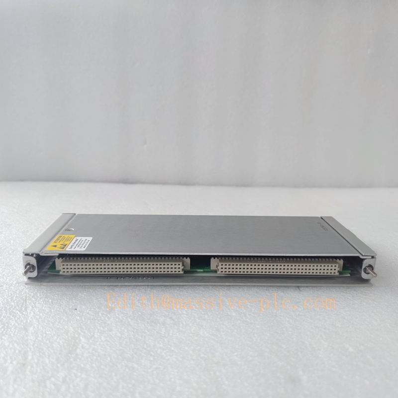
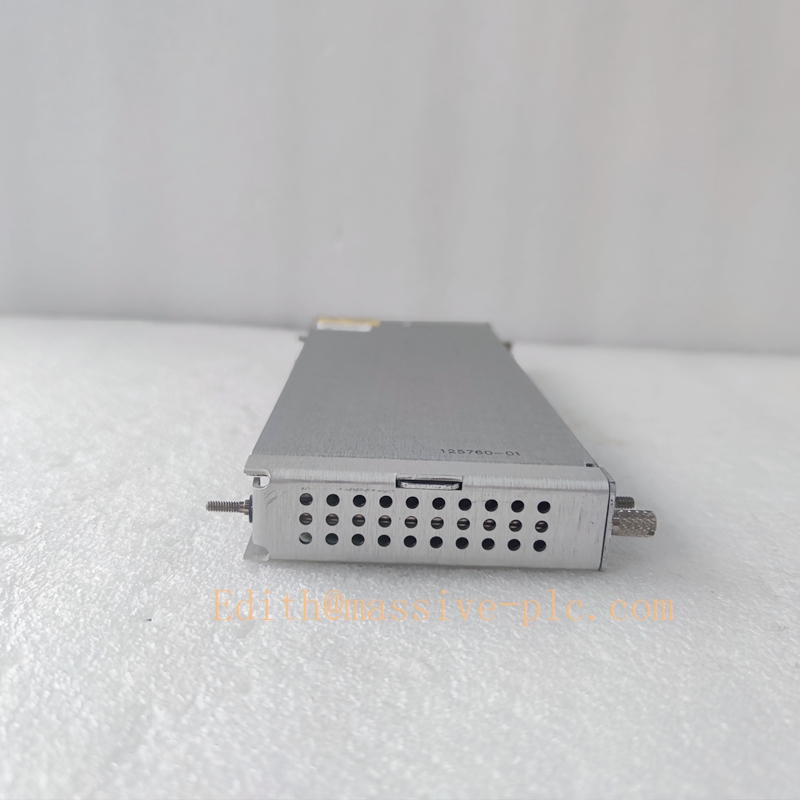
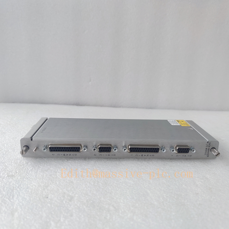
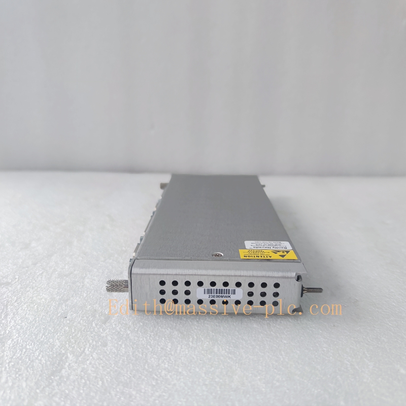
Bently Nevada 125760-01 Signal Conditioning / Interface Module Technical Documentation
Product Description
The Bently Nevada 125760-01 is a high-precision industrial signal conditioning and interface module specifically designed for the 3500 Machinery Protection System. As you have previously inquired about related 3500 series modules such as 125720-02 and 125768-01, this module serves a distinct function: it acts either as a dedicated vibration monitoring signal conditioning unit for critical rotating equipment, or as a versatile 3500/20 Rack Interface Module (RIM) variant for data management and communication. It is engineered to deliver exceptional signal integrity in harsh industrial environments where electromagnetic interference (EMI) and temperature extremes can compromise monitoring accuracy. Manufactured to stringent quality standards, it is widely deployed as a drop-in replacement for legacy signal conditioning units and as a core component in new installations requiring reliable data acquisition.
350020 125760-01
Technical Specifications
| Parameter | Official Specification |
|---|---|
| Manufacturer | Bently Nevada (Baker Hughes) |
| Part Number | 125760-01 |
| Primary Function | Signal Conditioning Adapter / Rack Interface Module |
| Measurement Range (Displacement) | 0 to 25.4 mm (1 inch) peak-to-peak |
| Frequency Response | 0.5 Hz to 10,000 Hz |
| Output Signal | 4-20 mA analog with HART protocol |
| Power Supply | 18 to 30 V DC |
| Input Impedance | 21.8 kΩ (minimum) |
| Digital I/O Capability | 16 Digital Inputs + 16 Digital Outputs |
| Communication Protocols | RS-232, RS-485, Modbus RTU |
| Operating Temperature Range | -40°C to +85°C |
| Storage Temperature Range | -55°C to +105°C |
| Enclosure Rating | IP67 (Dustproof and Water Immersion Resistant) |
| Housing Material | Stainless Steel |
| Dimensions (H x W x D) | 241.3 mm x 24.4 mm x 241.8 mm |
| Net Weight | 1.2 kg (some versions 1.8 kg) |
| Compliance | API 670, IEC 61000-6-2 (EMC Immunity) |
Key Features and Advantages
- Superior Signal Integrity in Noisy Environments: The module’s integrated EMI filtering circuit, as evidenced in your referenced case study (Indiana power plant), can reduce signal noise by up to 95%, effectively eliminating false alarms caused by electromagnetic interference from nearby high-voltage cables.
- Precision Impedance Matching: Designed for optimal compatibility with Bently Nevada’s full range of proximity probes (like the 3300 XL series), it eliminates signal distortion from impedance mismatches, ensuring measurement accuracy matches or exceeds factory specifications across the entire operating temperature range.
- Dual-Function Versatility: Can be configured either as a dedicated signal conditioner for vibration monitoring loops or as a standard Rack Interface Module (RIM), providing flexibility for system design and spare part inventory reduction.
- Robust Construction for Harsh Duty: The IP67-rated stainless steel enclosure provides superior protection against dust, moisture, and corrosive atmospheres, making it suitable for outdoor installations and extreme industrial conditions (-40°C operational).
- Proven Cost Savings: Field data demonstrates its ability to prevent costly false shutdowns (e.g., $250,000 per incident in the referenced case) by converting unreliable monitoring signals into actionable, trustworthy data for predictive maintenance decisions.
- Seamless System Integration: Supports industry-standard protocols (HART, Modbus), enabling straightforward integration with existing DCS, PLC, and SCADA systems without requiring additional protocol converters.
Application Fields
- Power Generation: Vibration signal conditioning for coal-fired and gas turbine generator sets, specifically to mitigate EMI from plant switchyards and high-voltage busbars, preventing spurious trips.
- Oil & Gas: Critical vibration monitoring for centrifugal compressors, pumps, and gas turbines in refineries and petrochemical plants, where signal reliability is paramount for safety and production continuity.
- Heavy Industry: Displacement and vibration monitoring for large rolling mills, fans, and blowers in metallurgy and mining, where equipment size and motor drives create significant electrical noise.
- System Modernization: A key component in upgrading legacy 3300/7200 series monitoring systems to the 3500 platform, allowing reuse of existing transducer infrastructure (probes, cables) to minimize upgrade costs and downtime.
- Aerospace & Test Rigs: High-frequency vibration data acquisition for precision test stands and research facilities requiring clean, accurate signals from non-contact probes.
Related Product Recommendations
- 3300 XL 8mm / 11mm Proximity Probes (e.g., 330103-00-xx-xx): The primary transducers that pair with the 125760-01 for displacement measurement, providing the raw eddy current signal the module conditions.
- 3500/42M Vibration Monitor Module (e.g., 138708-01): Processes the conditioned 4-20 mA signal from the 125760-01, providing vibration alarms, trends, and dynamic waveform data. This complements the signal conditioning function you’ve explored in other modules.
- 3500/92 Communication Gateway: If the 125760-01 is used in its RIM capacity, this gateway can expand connectivity to Ethernet-based networks (Modbus TCP/IP, EtherNet/IP) for plant-wide data integration.
- System 1® or System 1® Evolution Software: The enterprise-level condition monitoring software platform that aggregates and analyzes data from all 125760-01 equipped racks, enabling advanced diagnostics and predictive maintenance.
350020 125760-01
Installation and Maintenance Guidelines
6.1 Installation Procedure
- Site Preparation: Identify a mounting location that minimizes the cable run between the proximity probes and the module, and ensures a distance of at least 0.5 meters from 25kV or higher power cables to reduce EMI, as per your previous case study insights.
- Module Mounting: Securely mount the module on a DIN rail or panel using the provided hardware. Ensure the stainless steel enclosure is properly grounded to the plant’s protective earth system.
- Wiring Connection:
- Power: Connect the 18-30 VDC power supply using shielded cable, observing correct polarity.
- Signal Input: Connect the shielded cable from the proximity probe to the designated terminal. Ensure the shield is grounded at the module end only.
- Signal Output: Connect the 4-20 mA output terminals to the corresponding input on the monitoring system (e.g., 3500 rack monitor module or DCS AI card).
- Communication: If used as a RIM, connect the RS-232/485 or Modbus cables to the host system.
- Power-Up & Verification: Apply power and verify the module’s status indicator. Use a multimeter to check the output current corresponds to the expected probe gap voltage.
6.2 Commissioning & Configuration
- Software Setup: If configurable parameters exist (e.g., via HART communicator or dedicated software), set the correct probe sensitivity (typically 200 mV/mil) and measurement range.
- Gap Calibration: Perform a static mechanical gap calibration using a dial indicator. Adjust the probe position until the module’s 4-20 mA output correctly reflects the actual physical gap.
- System Integration Test: Introduce a known vibration or displacement (e.g., using a calibration shaker) and verify the signal is correctly received and displayed by the connected monitoring system.
6.3 Routine Maintenance
- Quarterly Check: Visually inspect all cable connections for tightness and corrosion. Verify the IP67 seal integrity if installed in harsh environments.
- Bi-Annual Check: Measure the output signal noise floor with machinery at rest. Compare it to baseline readings; a significant increase may indicate degrading EMI filtering or cable issues.
- Annual Check: Perform a full calibration check against a known reference standard to ensure measurement accuracy remains within specified tolerances.
6.4 Troubleshooting Guide
- Symptom: Erratic or Noisy Signal
- Action 1: Check cable routing. Ensure separation from power cables as per installation guideline.
- Action 2: Verify shield grounding is single-point at the module.
- Action 3: Test with a known-good probe and cable to isolate the fault.
- Symptom: No Output Signal
- Action 1: Verify power supply voltage is within 18-30 VDC.
- Action 2: Check for open or short circuits in the probe and cable.
- Action 3: If used as a RIM, verify communication settings (baud rate, parity) match the host system.
- Symptom: Incorrect Reading
- Action 1: Re-perform the mechanical gap calibration.
- Action 2: Verify the configured probe sensitivity in the software matches the physical probe installed.


 Start Chat




