
Description
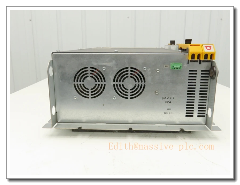
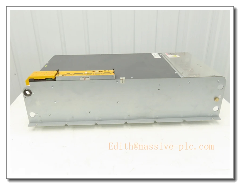
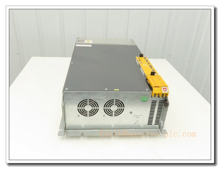
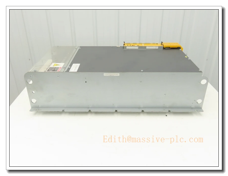
Baumüller BUM64F-300/390-54-M-038 BUM64F High Power Mono Servo Power Unit
Product Core Introduction
The BUM64F-300/390-54-M-038 is a high-power standalone mono power unit from Baumüller BUM64F family. Model coding: 300A continuous / 390A peak output, 540V DC-link, F = fan-cooled version. It requires a separate BUS6-T control cassette to implement torque, velocity and position closed-loop control for large synchronous servo / spindle motors. It accepts 3-phase 400~480VAC mains supply, built-in large brake chopper for heavy regenerative loads, high-current IGBT power stage and comprehensive multi-level fault monitoring. Widely deployed in heavy-duty machine tools, large gantries, metal forming & printing converting lines. This series is OEM end-of-life; available stock consists of fully tested refurbished / surplus spare units for legacy machine maintenance and retrofits.
BUM64F-300-390-54-M-038
Main Technical Specifications
| Technical Parameter | Specification Value |
|---|---|
| Model | BUM64F-300/390-54-M-038 (Baumüller) |
| Product Type | High-power mono servo power unit (needs BUS6-T control card) |
| Continuous Output Current | 300 A |
| Peak Output Current | 390 A |
| DC Link Voltage | 540 VDC |
| Mains Input | 3×400–480 VAC, 50/60 Hz |
| Auxiliary Control Supply | 24 VDC ±20% |
| Output Frequency | 0 ~ 300 Hz |
| Control Cassette | BUS6-T (separate plug-in controller) |
| Control Modes | Torque / Velocity / Position control |
| Feedback | Resolver / Incremental / SSI encoder (depends on BUS6-T configuration) |
| Protection | Overcurrent, overvoltage, undervoltage, over-temperature, earth fault, phase loss, E-stop interlock |
| Cooling | Forced fan cooling |
| Operating Temperature | 0 ℃ ~ +40 ℃ (cabinet ambient) |
| Storage Temperature | -40 ℃ ~ +85 ℃ |
| Operating Humidity | 5% ~ 85% RH, non-condensing |
| Mounting | Cabinet panel mount |
| Compliance | CE, UL |
| Lifecycle Status | OEM Discontinued, aftermarket tested spare |
Brand Same‑Series Model Recommendation
- BUM64F-200/260-54: Medium high-power variant, 200A continuous /260A peak, for mid-size heavy axes.
- BUM64F-400/520-54: Higher current BUM64F unit, 400A continuous, for ultra-heavy inertia loads.
- BUM63 series: Mid-power mono power unit, smaller footprint, lower current rating.
- b maXX 6500: Modern Baumüller high-power servo platform, recommended for long-term system migration.
Professional Quality Control Test Standard Operating Procedures (SOP)
5.1 Incoming & Visual Inspection
Inspect high-current IGBT modules, large DC-link capacitors, cooling fans, heavy-duty terminal blocks and BUS6-T slot. Visual check for bulging capacitors, burnt PCB traces, cracked solder, oxidation on high-current terminals. Insulation and hi-pot test for power circuits. Batch traceability records retained.
5.2 Low-Voltage Power-On Pre-Test
Apply 24VDC control supply. Verify power-on self-test, LED status, BUS6-T card detection and communication handshake. Check fan rotation and abnormal heating before applying high-voltage 3-phase mains.
5.3 Burn-in Test
72-hour cyclic powered burn-in at 40°C ambient. Run dynamic load cycles with matched high-power servo motor. Monitor DC bus ripple, output current, temperature rise and fault logs. Units with intermittent trips, current ripple or thermal drift are rejected.
5.4 Full Functional Calibration & Parameter Test
Use power analyzer, encoder/resolver simulator and oscilloscope to calibrate current loop, velocity loop and position loop response. Validate all protection functions: OC, OV, UV, overtemperature, earth fault, phase loss and emergency stop. Verify analog/digital setpoint and motion profile execution.
5.5 Environmental Stress Screening
Temperature cycling (0 ℃ ↔ +40 ℃), humidity soak and low-level random vibration per IEC 60068, to verify mechanical integrity and power stage stability simulating shipping and factory heavy-duty operation.
5.6 Final Acceptance Test
Full system test with control cassette and matching large Baumüller servo motor. Execute jogging, positioning, high-speed spindle profiling and emergency shutdown test. Verify fault code reporting. Complete appearance, label and accessory inspection before heavy-duty anti-shock packing.
New Unit Installation Guidelines
6.1 Pre-Installation Preparation
- Lock-out/tag-out (LOTO) the 3-phase mains supply. Confirm DC-link capacitors are fully discharged.
- Wear anti-static wristband and gloves; use anti-static mat when handling control cassette.
- Inspect unit for mechanical damage, capacitor swelling and burnt high-current terminals. Confirm compatibility with existing card and servo/spindle motor.
- Check cabinet cooling capacity, fan clearance, heavy-gauge cable sizing and grounding design.
6.2 Hardware Installation
- Mount the high-power servo power unit on cabinet heavy-duty backplane, fasten mounting screws to specified torque and maintain required ventilation clearance.
- Insert control cassette into the slot and lock securely.
- Wire 3-phase mains, heavy-gauge motor power cable, resolver/encoder feedback cable, 24VDC control power, command signals and E-stop interlock strictly following Baumüller wiring diagram.
- Use shielded cables for encoder and analog signals; separate low-level control wiring from high-power motor cables. Ensure protective earth connection is low impedance and properly sized for high current.
6.3 Post-Installation Commissioning
- Double-check wiring, grounding and interlock continuity before energizing.
- Apply 24VDC control power first, run self-test and check fault LED status.
- Energize 3-phase mains, input motor nameplate parameters and run motor identification auto-tune.
- Perform low-speed jog test, verify encoder/resolver direction and position feedback. Tune current, velocity and position servo loops.
- Run continuous heavy-load motion profile test for 30–60 minutes before releasing machine to production.
Important Safety Note: This high-current unit contains dangerous high-voltage DC-link capacitors. Hazardous residual voltage remains after power-off. Only qualified high-power drive automation technicians can perform installation and service.
BUM64F-300-390-54-M-038
Application Scenarios & Product Characteristics
7.1 Application Scenarios
- Heavy-duty CNC machine main spindle and large linear gantry axes
- Metal forming, press & bending machinery
- Large web printing and converting production lines
- Heavy material handling, large palletizing automation
- Legacy Baumüller BUM64 high-power motion system spare replacement
7.2 Key Characteristics
- Modular architecture: high-power mono power unit + plug-in control cassette
- 300A continuous / 390A peak output for ultra-high dynamic acceleration of large inertia loads
- 540V DC-link design for 400~480V class large spindle / servo motors
- Integrated high-capacity brake chopper for heavy regenerative energy
- Forced fan cooling for continuous high-current operation
- Multi-layer protection for overcurrent, earth fault, phase loss and over-temperature
- Supports resolver or incremental/SSI encoder feedback
- Robust heavy-duty cabinet design for continuous 24/7 factory operation
- Critical spare for legacy Baumüller BUM64 high-power motion systems (OEM discontinued)
FAQ (Frequently Asked Questions)
Q1: Power on reports DC bus overvoltage fault. A1: Check 3-phase input voltage, line reactor and brake resistor sizing/connection. Verify deceleration ramp; inspect aging DC-link capacitors.
Q2: Servo / spindle jitters and position fluctuates during operation. A2: Check encoder/resolver cable shielding, grounding and connector pins. Re-tune servo loops. Check mechanical coupling backlash or axis binding.
Q3: Drive trips overcurrent during acceleration. A3: Confirm motor nameplate parameters match drive configuration. Inspect motor winding insulation and cable short circuit. Reduce acceleration rate or check mechanical friction.
A4: Check control cassette seating and slot contacts. Inspect card edge connector for oxidation. Confirm firmware compatibility between and power unit.
Q5: Can I replace BUM64F-300/390-54-M-038 directly with BUM64F-400/520-54? A5: Mechanical footprint is compatible, but current rating increases significantly. Motor parameters, brake resistor and servo tuning must be fully revalidated.
Q6: Hot swap allowed? A6: NOT PERMITTED. Cut off all 3-phase power and fully discharge DC bus before opening enclosure or swapping control cassette.



 Start Chat




