

Description
Applied Materials (AMAT) 0090-76110 Synergy UP 6U VME Single Board Computer (SBC)
Product Core Introduction
The 0090-76110 is a 6U VME single-board computer (SBC) designed by Applied Materials for the Synergy / Synergy UP semiconductor process platform. It serves as the primary system controller for wafer etch, deposition and chamber subsystems, running real-time process control, recipe execution, equipment state management and SECS/GEM host communication. Equipped with PowerPC processor, onboard flash storage and SDRAM memory, this board integrates VME bus interface, serial ports and front-panel diagnostic LEDs. It is the core VME CPU board inside legacy AMAT process chambers. This part is OEM end-of-life; available stock consists of fully tested refurbished and surplus spare units for fab maintenance and tool refurbishment.
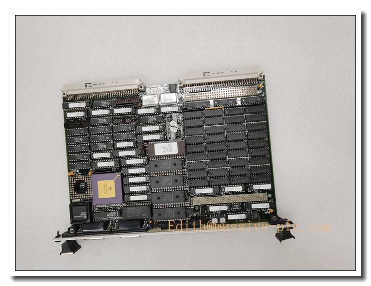
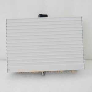
0090-76110 VME PCB
Main Technical Specifications
| Technical Parameter | Specification Value |
|---|---|
| Part Number | 0090-76110 (Applied Materials) |
| Product Type | 6U VME Single Board Computer (SBC), Synergy UP CPU |
| CPU | Motorola PowerPC |
| Onboard Memory | SDRAM + Flash non-volatile storage |
| Bus Interface | VMEbus (IEEE 1014) |
| Front Panel I/O | Serial port, diagnostic LED indicators, reset switch |
| Onboard Functions | Real-time process control, recipe storage, SECS/GEM communication, VME bus master/slave |
| Power Input | ±5VDC, ±12VDC from VME backplane |
| Operating Temperature | 10 ℃ ~ +50 ℃ (Cleanroom environment) |
| Storage Temperature | -40 ℃ ~ +85 ℃ |
| Operating Humidity | 5% ~ 85% RH, non-condensing |
| Form Factor | 6U VME Eurocard |
| Net Weight | ~0.55 kg |
| Compliance | SEMI S2, CE, ISO 1 cleanroom compatible |
| Lifecycle Status | OEM Discontinued, aftermarket tested spare only |
Brand Same‑Series Model Recommendation
- 0090-76109: Earlier revision Synergy VME CPU board, pin-compatible partial replacement, older firmware version.
- 0090-76111: Updated Synergy UP variant, upgraded memory capacity, enhanced firmware, drop-in upgrade for compatible chassis.
- 0090-02720: AMAT alternative VME CPU for older Mark IV chamber controllers, different firmware platform.
- Modern AMAT x86 controller: Newer generation controller for long-term tool migration, replacing legacy VME Synergy architecture.
Professional Quality Control Test Standard Operating Procedures (SOP)
5.1 Incoming & Visual Inspection
Inspect PCB, processor, memory chips, flash ICs, VME edge connector, front panel components and conformal coating. Visual check for burnt traces, swollen capacitors, cracked solder, connector pin damage and contamination. Continuity and isolation test for VME bus power and signal lines. Retain batch traceability records.
5.2 Low-Voltage Power-On Pre-Test
Power the board via VME test fixture. Verify boot sequence, front panel LED status, memory detection and firmware initialization. Check for abnormal heating or bus errors before running full system test.
5.3 Burn-in Test
48-hour continuous powered burn-in at 40°C ambient. Run cyclic VME bus read/write, memory stress test and firmware background diagnostics. Monitor bus communication stability; reject boards with intermittent bus faults, memory errors or boot failures.
5.4 Full Functional Calibration & Parameter Test
Use VME test chassis to validate VME master/slave operation, serial communication, memory read/write and watchdog timer. Load native Synergy firmware, verify recipe load function, alarm logging and SECS/GEM basic handshake. Validate all diagnostic LED status codes.
5.5 Environmental Stress Screening
Temperature cycling (10 ℃ ↔ +50 ℃), humidity soak and low-level random vibration per IEC 60068 to verify mechanical integrity and signal stability under shipping and fab operating stress.
5.6 Final Acceptance Test
Install the board into matching AMAT Synergy VME card cage. Test full chamber controller simulation, VME backplane communication with peripheral I/O boards. Complete appearance, label and accessory inspection. Passed units are packed with anti-static and anti-vibration packaging.
New Board Installation Guidelines
6.1 Pre-Installation Preparation
- Power down the entire VME chassis and implement LOTO procedure. Confirm backplane power is fully removed.
- Wear anti-static wristband and gloves, use anti-static mat for handling the PCB.
- Inspect 0090-76110 for scratches, bent edge connector pins or component damage. Confirm firmware revision compatibility with existing chamber software.
- Check VME card cage backplane, cooling fan and airflow condition.
6.2 Hardware Installation
- Align the 6U VME board with the card cage guide rails.
- Insert smoothly into the VME backplane until fully seated. Tighten front panel mounting screws.
- Verify front panel serial port connection if required.
- Confirm adequate airflow; do not block ventilation around the board.
6.3 Post-Installation Commissioning
- Double-check all VME backplane slots and power wiring before energizing.
- Apply chassis power and observe boot sequence and LED status.
- Confirm firmware boots successfully, verify detection of other VME peripheral boards on backplane.
- Load chamber recipe, verify recipe execution, alarm reporting and host SECS/GEM communication.
- Run continuous 30–60 minutes chamber simulation test before returning the wafer tool to production.
Important Safety Note: This PCB is sensitive ESD component. All handling must follow cleanroom ESD control procedure. VME backplane carries DC power; always power off chassis before board insertion or removal.
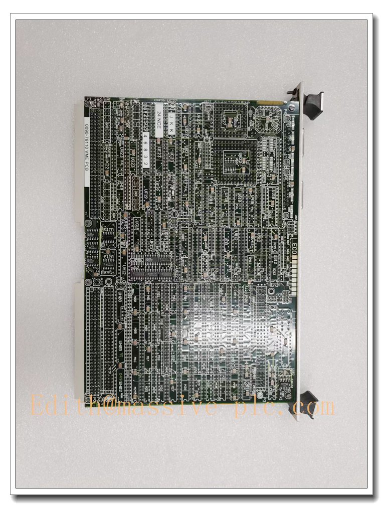
0090-76110 VME PCB
Application Scenarios & Product Characteristics
7.1 Application Scenarios
- Applied Materials Synergy / Synergy UP semiconductor wafer process chambers
- Plasma etch, CVD and thin-film deposition equipment
- Chamber recipe management, real-time process sequencing
- Fab host communication via SECS/GEM
- Legacy AMAT semiconductor tool spare replacement
7.2 Key Characteristics
- 6U VME single-board computer, native Synergy platform CPU controller
- PowerPC real-time processor for deterministic process control
- Onboard non-volatile flash storage for recipe and firmware
- VME bus master/slave capability to control peripheral I/O, analog and digital boards
- Front panel LEDs for quick diagnostic status checking
- Conformal coated PCB for cleanroom fab environment
- Critical spare for legacy Applied Materials Synergy process tools (OEM discontinued)
FAQ (Frequently Asked Questions)
Q1: After replacement, board fails to boot and front LED stays red. A1: Check VME backplane power and edge connector pins. Inspect for bent pins or oxidation. Confirm firmware version compatibility with chamber software. Reset chassis and retry boot.
Q2: VME bus communication error, cannot detect other VME peripheral boards. A2: Check seating of all VME boards in the card cage. Inspect backplane for damage. Verify termination settings on VME bus. Check for bus noise or grounding issues.
Q3: Recipe loading fails or data corruption occurs. A3: Check onboard flash health. Verify ESD damage. Re-flash compatible firmware version. Check memory integrity via diagnostic routine.
Q4: SECS/GEM communication to host tool is intermittent. A4: Check serial cable shielding and grounding. Verify baud rate and communication parameter matching. Check firmware revision compatibility.
Q5: Can I replace 0090-76110 directly with 0090-76111? A5: Mechanical form factor and VME pinout are compatible, but firmware must be validated. Chamber software may require configuration update after swap.
Q6: Hot swap VME board allowed? A6: NOT PERMITTED. Always power off VME chassis before installing or removing the VME board to avoid ESD and backplane damage.


 Start Chat




