Description
ALSTOM 12004-102-01 VPS BOARD VER.C Full English Technical Document
Product Title
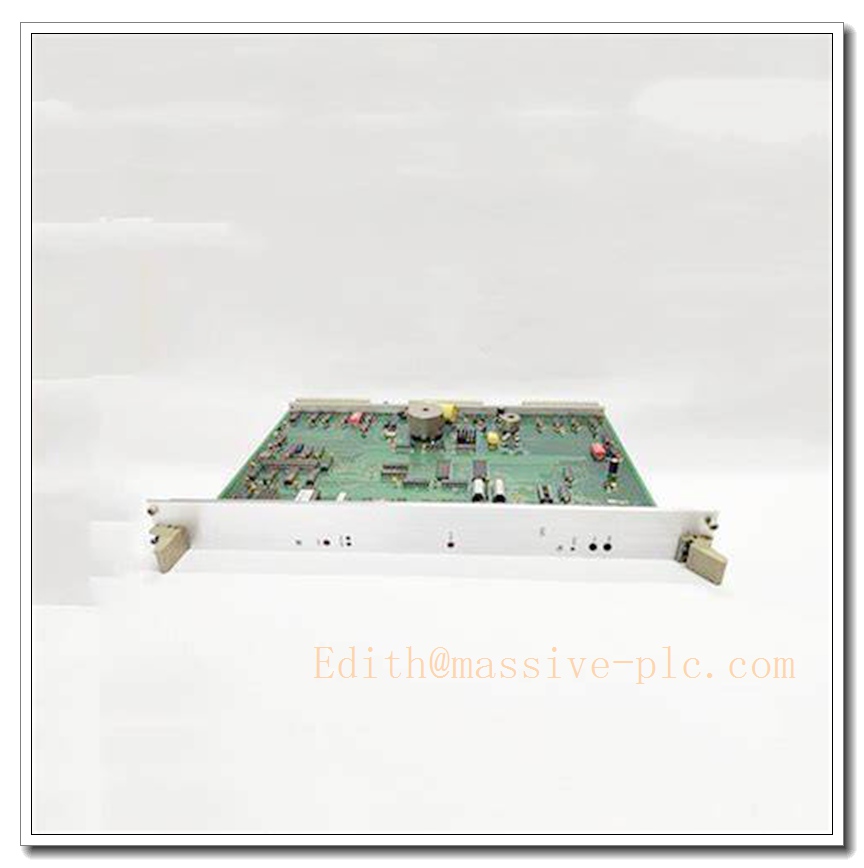
ALSTOM 12004-102-01 VPS BOARD VER.C Industrial Power Generation Control VPS Interface/IO Module
Product Description
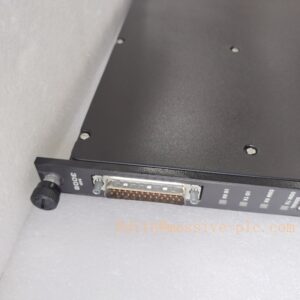
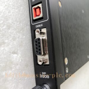
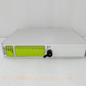
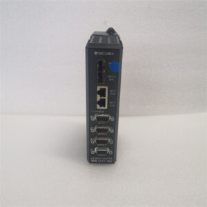
The ALSTOM 12004-102-01 VPS BOARD VER.C is a rugged, industrial-grade dedicated interface/IO board module purpose-built for critical power generation and heavy industrial control scenarios. As a core signal processing hub for ALSTOM gas/steam turbine control systems and mainstream DCS/PLC platforms (including GE Mark VIe), it undertakes full signal conversion, electrical isolation, signal conditioning, and protocol adaptation tasks between field sensors/actuators and upper-level main controllers. The VER.C iteration delivers significantly enhanced operational stability and cross-system compatibility compared to earlier versions, making it a trusted field-proven spare part for legacy ALSTOM power plant control system maintenance and retrofitting projects.
Technical Specifications
- Manufacturer: ALSTOM
- Part Number: 12004-102-01 VPS BOARD VER.C
- Product Type: Industrial VPS Interface/IO Module
- Core Functions: Field signal conversion, electrical isolation, signal conditioning, multi-protocol adaptation
- Communication Interfaces: 3 independent RS232/RS485 serial ports
- Serial Port Baud Rate Range: 300~9600 bps
- Communication Bit Error Rate: ≤ 10⁻⁴
- Operating Voltage Range: 10–30 V DC
- Power Consumption: 1W (standby), 2W (full-load transmission)
- Operating Temperature Range: -20°C to +70°C
- Ambient Humidity Rating: ≤95% non-condensing, suitable for non-corrosive, non-explosive industrial environments
- Core Hardware: Industrial-grade embedded CPU, supports RAM expansion and EEPROM non-volatile data storage
- Redundancy Support: Compatible with dual-CPU, dual-communication-channel redundant system configurations
- EMC Performance: Strong industrial-grade electromagnetic interference resistance
- Mean Time Between Failures (MTBF): ≥70000 hours
- Warranty Period: 12 months from factory delivery
Key Features and Advantages
- Native seamless compatibility with ALSTOM gas/steam turbine control systems and GE Mark VIe DCS platforms eliminates the need for third-party signal conversion hardware, enabling direct drop-in replacement for legacy VPS interface modules
- Multi-channel independent serial port design supports simultaneous connection to multiple field sensor and actuator devices, drastically reducing the number of required signal conversion modules in large-scale distributed control systems
- Built-in full electrical isolation architecture effectively blocks industrial site surge voltage and electromagnetic interference, preventing signal anomaly and system crash risks caused by field electrical noise
- VER.C version optimized hardware design delivers significantly improved operational stability and cross-system compatibility compared to earlier VER.A/VER.B iterations, drastically reducing field fault rates
- Industrial-grade embedded CPU with EEPROM non-volatile data storage ensures critical control configuration parameters are not lost during unexpected power outages, supporting uninterrupted system operation
- Full redundant configuration compatibility supports dual-CPU and dual-communication-channel hot-standby operation, eliminating single-point hardware failure risks for safety-critical power generation control systems
- Ultra-low power consumption design reduces total system power load and heat generation, extending the service life of on-site control cabinet cooling infrastructure
- Wide 10–30V DC universal power input range adapts to diverse industrial power supply environments, eliminating the need for extra dedicated power conversion modules
Model Parameter Details
| Part Number | Core Configuration |
|---|---|
| 12004-102-01 VPS BOARD VER.C | Standard VPS interface/IO module, 3 RS232/RS485 serial ports, 10-30V DC power supply, industrial embedded CPU, redundant system support, VER.C optimized stability |
Application Fields
- ALSTOM gas/steam turbine control system field signal processing and transmission
- Large-scale thermal power plant DCS distributed control system signal interconnection
- New energy wind farm and photovoltaic station grid interconnection control system signal supervision
- Rail transit traction control system industrial signal conditioning and adaptation
- Heavy industrial metallurgy large-scale equipment distributed control system IO expansion
- Legacy ALSTOM power generation control system spare part replacement and retrofitting scenarios
Related Product Recommendations
- ALSTOM Turbine Control System Main Processing Unit
- ALSTOM 12004 Series VPS Board Dedicated DIN Rail Mounting Bracket Kit
- ALSTOM Redundant 24V DC Power Supply Unit for Control Cabinets
- ALSTOM Dedicated Shielded Industrial Serial Communication Cable Kit
- ALSTOM Power Generation Control System Official Configuration and Diagnostics Software
- ALSTOM Industrial Signal Surge Protection Barrier Module
- ALSTOM High-Density Analog Input/Output Expansion Module
- ALSTOM 12004-102-01 VPS Board Field Calibration and Debugging Toolkit
Pre-Installation Safety Precaution
Before initiating any hardware installation or wiring procedures, ensure all connected power generation control systems are fully de-energized, locked out, and tagged in strict compliance with local power plant industrial safety regulations. Only qualified power plant automation and electrical maintenance personnel with professional high-voltage operation certification are authorized to perform installation work. Never insert or remove the module while the system is connected to live high-power field sensor or actuator circuits, as improper hot-plug operations may cause permanent hardware damage or unplanned turbine shutdown safety risks.
Hardware Installation Steps
- Select a dedicated mounting position on the DIN rail inside the industrial control cabinet, ensuring sufficient ventilation clearance around the module, avoiding direct exposure to high-temperature radiation, moisture, or corrosive industrial fumes
- Secure the module firmly to the DIN rail, confirming the mechanical locking mechanism engages completely to prevent vibration-induced disconnection during long-term turbine operation
- Connect the 10–30V DC power wiring to the module’s dedicated power terminals, verifying the power supply voltage matches the module’s rated specification before applying power
- Terminate all field sensor and actuator signal wiring strictly following the official ALSTOM wiring schematic, confirming signal polarity, shielding single-point grounding, and terminal labeling accuracy
- Wire all upper-level DCS/PLC system communication cabling with proper shielding grounding, to eliminate strong electromagnetic interference impact on serial signal transmission stability
- Torque all wiring terminals to the specified torque values, and install dedicated cable strain relief for all external field wiring runs
System Configuration Workflow
- Power on the module after completing all wiring checks, confirm the power indicator LED on the board illuminates in normal steady state with no active fault alarms
- Connect the configuration engineering workstation to the module’s service serial port, launch the official ALSTOM power generation control system configuration software to establish stable point-to-point communication
- Complete basic device parameter setup, including module identification, local time synchronization, and each serial port’s corresponding field device address allocation configuration
- Calibrate all signal input and output channel scaling parameters, matching the connected field sensor and actuator operational ranges to ensure signal conversion accuracy
- Configure serial communication protocol parameters, enabling seamless real-time data exchange between the new VPS board and the upper-level DCS/PLC main control unit
- Customize communication fault alarm thresholds and redundant switchover logic according to specific on-site power generation process requirements, then save the full configuration profile to the module’s EEPROM non-volatile memory
Post-Installation Verification Checklist
- Confirm all on-board status LEDs operate in normal state, with no persistent active fault or warning indicators
- Validate that real-time sampled field signal values fully match the expected on-site process parameter readings
- Perform full serial communication testing, confirming the module transmits accurate, stable data to the upper-level control system with no data loss or bit error anomalies
- Test the built-in redundant switchover function manually, confirming the system seamlessly switches to the backup VPS board without interrupting normal control operation
- Verify end-to-end communication connectivity between the module and the ALSTOM/GE Mark VIe main control unit, confirming complete, uncorrupted real-time signal transmission
- Trigger the full system power cycle test, confirming the module resumes normal operation automatically after power restoration without configuration loss or communication fault events