
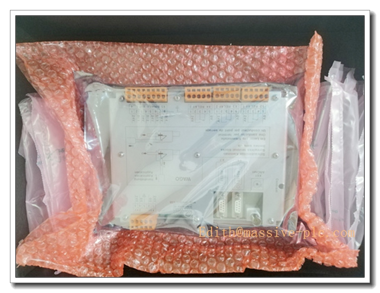
Description
AFC094AE02 Product Technical Manual
Product Core Introduction
The AFC094AE02 is an ABB Bailey analog input terminal unit, belonging to the INFI 90 distributed control system series. It serves as the field signal conditioning terminal assembly for analog input modules, converting raw field sensor signals into standardized isolated signals for the DCS controller. This unit provides surge suppression, signal filtering and channel isolation for 4–20mA analog field signals. Widely used as spare replacement parts in legacy power, pulp & paper and chemical INFI90 control racks, it delivers reliable signal conditioning under continuous long-term plant operation.
Main Technical Specifications
- Model: AFC094AE02
- Power Supply: 24VDC, operating range 18–30VDC
- Signal Type: 4–20 mA analog input
- Number of Channels: 16 channels
- Channel Isolation: Galvanic isolation per channel
- Surge Protection: Built-in transient suppression for field wiring
- Backplane Interface: ABB INFI90 rack bus
- Operating Temperature: 0°C ~ +60°C
- Storage Temperature: -40°C ~ +85°C
- Relative Humidity: 5%–95% RH, non-condensing
- Dielectric Withstand Voltage: 1500V AC between field side and control circuit
- Protection Class: IP20 (cabinet rack installation only)
- MTBF: ≥85,000 hours
- Mounting: Standard INFI90 rack slot mounting
- Net Weight: 1.32 kg
- Status Indicators: Channel fault LED, power LED
Recommended Homologous Series Models
-
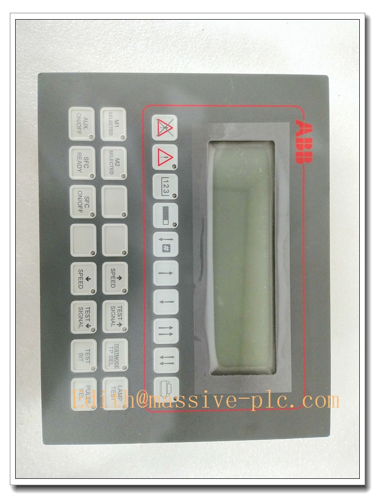
AFC094AE02
Professional Quality Control & Test Standard Operating Procedures (SOP)
4.1 General Test Standard
All AFC094AE02 units are inspected in compliance with ISO9001, IEC61131 and IEC61000 EMC standards. A unique serial number is assigned for full product lifecycle traceability.
4.2 Core Test SOP
- Visual & Mechanical Inspection: Examine housing, terminal blocks, PCB and backplane connectors for scratches, cracks, solder defects and bent pins; verify mechanical dimensions and rack rail fit against engineering drawings.
- Power-On Basic Function Test: Apply minimum, rated and maximum 24VDC supply; confirm power indicator operates normally; detect overcurrent or short-circuit conditions.
- Channel Signal Calibration Test: Inject precision 4–20mA reference signal to each of the 16 channels; validate sampling accuracy, check for crosstalk between adjacent channels.
- Backplane Bus Communication Test: Insert the unit into INFI90 test rack; verify cyclic data exchange with controller, monitor bus error counters.
- EMC Immunity Test: Conduct ESD, electrical fast transient burst, surge and radiated interference tests per IEC61000 to avoid false channel alarms and signal distortion.
- Temperature Cycling Test: 0°C ↔ +60°C thermal cycling for 40 cycles, 2 hours per cycle; check signal drift and connector reliability.
- Vibration & Shock Test: 10–150Hz sinusoidal vibration and mechanical shock test to validate solder joint and connector integrity.
- Continuous Burn-In Aging: 160 hours burn-in at 55°C with all channels loaded; monitor signal stability and temperature rise to screen intermittent hidden faults.
- Final Calibration & Packaging: Recheck channel accuracy, record serial number, pack with anti-static material and attach inspection certificate.
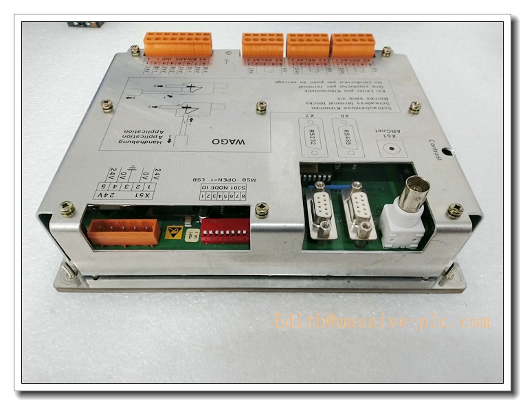
AFC094AE02
New Module Installation Guidelines
5.1 Pre-installation Preparation
Cut off rack and backplane power; verify model and serial number match purchase order; inspect anti-static packaging and connector integrity. Wear anti-static wristband before touching PCB components. Prepare screwdriver, torque screwdriver and precision signal source for commissioning.
5.2 Installation Steps
- Open the target slot cover on INFI90 rack; align AFC094AE02 with rack guide rails.
- Slide the unit fully into the slot until the backplane connector is securely engaged.
- Tighten front panel retaining screws to specified torque to prevent loosening caused by equipment vibration.
- Route field 4–20mA sensor wiring to terminal blocks; separate signal cables from high-power cables to reduce electromagnetic interference.
- Tighten terminal screws to recommended torque; confirm no bare copper exposure and correct wiring polarity.
5.3 Post-installation Commissioning
Restore rack power and power up the terminal unit; observe LED indicators to confirm normal power status. Use engineering workstation to read module diagnostics and perform point-by-point channel calibration. Run continuous 60-minute stability test; check signal sampling quality and bus communication before putting online.
Application Scenarios & Product Features
6.1 Core Application Scenarios
- Thermal power plant boiler, turbine and auxiliary system analog signal collection
- Pulp & paper mill DCS process monitoring racks
- Petrochemical continuous process pressure, flow and temperature measurement
- Cement plant kiln parameter monitoring and analog signal conditioning
- Legacy industrial system spare replacement and cabinet retrofit
6.2 Core Product Features
- 16-channel 4–20mA analog input terminal unit designed for ABB DCS
- Per-channel galvanic isolation, effectively suppress ground loop interference
- Built-in surge and transient protection to defend field wiring induced voltage spikes
- Integrated signal filtering for stable sensor measurement in noisy industrial sites
- Rack-mounted design, directly compatible with standard control racks
- Channel-level fault LED indication for fast field troubleshooting and maintenance
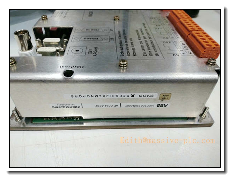
AFC094AE02
Frequently Asked Questions (FAQ)
Q1: Power LED does not illuminate after rack installation A1: Check rack 24VDC supply voltage and polarity; inspect loose backplane contact or damaged wiring; measure terminal voltage. If input voltage is normal while LED remains off, replace the terminal unit.
Q2: Individual analog channel reports fault alarm A2: Inspect field sensor wiring for short circuit or ground fault; verify transmitter power supply; swap channel wiring to differentiate between field transmitter fault and module hardware failure.
Q3: Analog reading fluctuates or drifts A3: Check shielding and grounding of field signal cable; eliminate ground loops; inspect terminal block oxidation; re-calibrate the affected channel via engineering software.
Q4: Intermittent backplane communication errors A4: Pull out and re-seat the unit fully in rack slot and retighten front screws; inspect backplane pins for corrosion; relocate cables away from high-current power lines.
Q5: Multiple channels trigger surge fault simultaneously A5: Check for lightning surge or voltage spike on field wiring; inspect grounding network of instrument cable; power down and reset the unit after transient event clears.
Q6: Can AFC094AE02 work with non-INFI90 controllers? A6: No. is dedicated terminal hardware for ABB DCS rack system. It cannot operate independently or interface directly with third-party PLC systems.
This document maintains identical structure and English technical tone consistent with PFV1401, PN1800, PNI800 and ABB 129740-002.

 Start Chat




