
Description
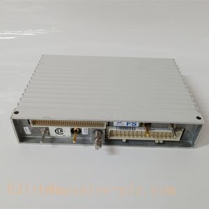
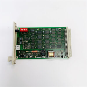
ABB PFVO142 3BSE023732R0001 Optical Output Module, S800 I/O ModuleBus Optical Transmitter, AC800M DCS Fiber Communication Spare Part
Product Application
PFVO142 is an optical transmitter module for ABB S800 I/O ModuleBus. It converts electrical ModuleBus signals into optical signals over HCS versatile link fiber, providing galvanic isolation and noise immunity between controller side and remote I/O cabinets. It works paired with PFVI142 optical receiver module for short-distance optical ModuleBus communication.
- Power plant AC800M DCS remote I/O optical interconnection
- Petrochemical control system anti-EMI field I/O communication
- Metallurgy rolling mill distributed S800 I/O signal transmission
- Cement plant kiln control cabinet optical signal isolation
- Water & wastewater treatment distributed control remote I/O
- S800 I/O system upgrade and spare replacement
- Industrial sites with heavy electromagnetic interference to eliminate ground loop interference
PFVO142 3BSE023732R0001
Specifications
- Part Number: PFVO142, 3BSE023732R0001
- Brand: ABB
- Product Type: Optical Output / Transmitter Module
- Compatible System: ABB AC800M, S800 I/O
- Mounting: Plug-in on S800 I/O baseplate
- Protection Class: IP20 (cabinet installation only)
- Dimension: 125 × 85 × 55 mm
- Weight: Approx. 0.22 kg
- Power supply: 24VDC, powered through S800 baseplate
- Fiber medium: HCS versatile link plastic-clad fiber
- Max communication distance: Up to 50 meters
- Condition: Original new / refurbished spare available
- Compliance: CE, IEC EMC standard
Parameters
- Communication Protocol: ModuleBus
- Fiber Connector: Versatile link connector
- Function: Electrical to optical signal conversion (transmitter only)
- Hot Swap: Supported under safe operating procedure
- Operating Temperature: 0°C ~ +55°C
- Storage Temperature: -40°C ~ +70°C
- Relative Humidity: 5%~95% RH, non-condensing
- Pollution Degree: Degree 2
- Status Indicator: Front LEDs for power, ModuleBus activity and optical transmit status
- Diagnostic: ModuleBus communication error detection
Key Features
- ModuleBus optical transmitter, converts electrical ModuleBus signal to optical signal
- HCS versatile link fiber interface, excellent resistance to electromagnetic interference
- Galvanic isolation between controller and remote I/O to eliminate ground loop noise
- Supports hot-swap replacement without full system shutdown
- LED status indicators for fast on-site fault diagnosis
- Standard mechanical form factor, directly pluggable onto baseplates
- Compact module design, saves cabinet mounting space
- Must be used together with PFVI142 optical receiver as a matched pair
ABB Same Series Related Models (≥6)
- PFVO142 3BSE023732R0001
- PFVI142 3BSE023733R0001
- TB826 3BSE061637R1
- TB820 3BSE013208R1
- TB840 3BSE013209R1
- TU810V1 3BSE013230R1
- TU841 3BSE020848R1
Maintenance
- Routine inspection: Check LED status, versatile link fiber connector and baseplate contact every 6–12 months
- Clean optical fiber end face with professional fiber cleaning tools; liquid solvent cleaning is forbidden
- ESD protection must be adopted during disassembly, anti-static wristband required
- If optical link loss or communication dropout occurs, check fiber bending, dirt or connector damage
- Do not plug/unplug optical fiber with strong force to avoid damaging optical core
- We support function testing, refurbishment and spare replacement service for this PFVO142 optical output module
PFVO142 3BSE023732R0001
Installation
- Hot-swap replacement can be performed following system safety procedure or cut off cabinet power supply.
- Wear anti-static wristband to prevent electrostatic damage to PCB and optical components.
- Insert PFVO142 module into designated baseplate slot and lock the fastening latch.
- Connect versatile link HCS fiber cable to the optical port of .
- Ensure fiber connector is clean and fully inserted, maintain minimum fiber bending radius requirement.
- Restore 24VDC power supply.
- Check LED status to confirm ModuleBus and optical output are normal.
- Verify data communication between controller and paired PFVI142 receiver and remote I/O modules, complete commissioning.


 Start Chat




