
Description
PCD232A / 3BHE022293R0101 Product Technical Specification & Operation Manual
Product Title
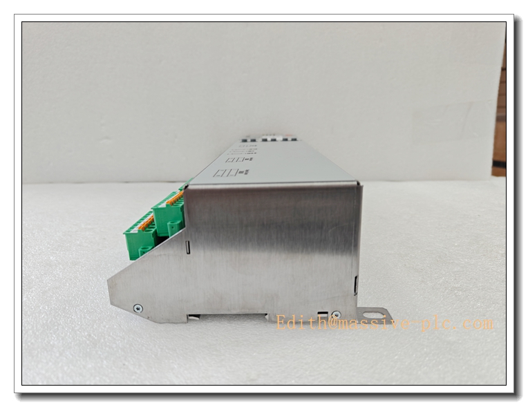
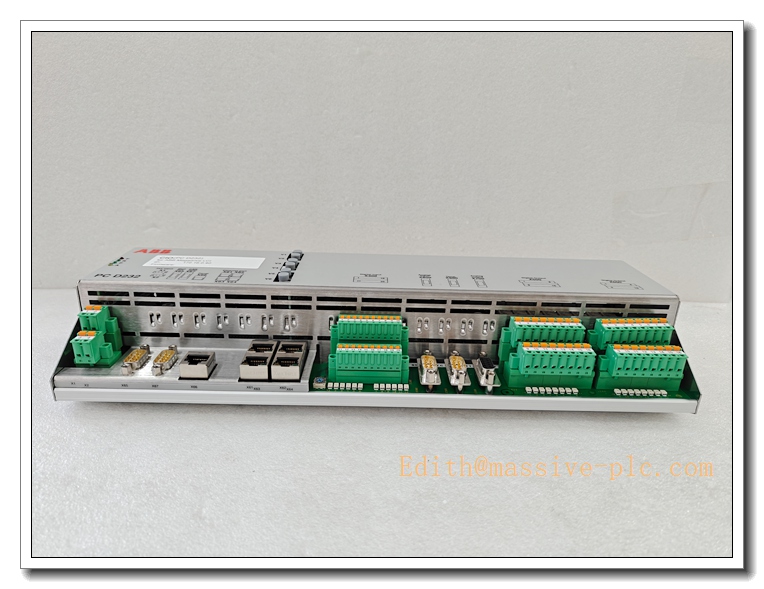
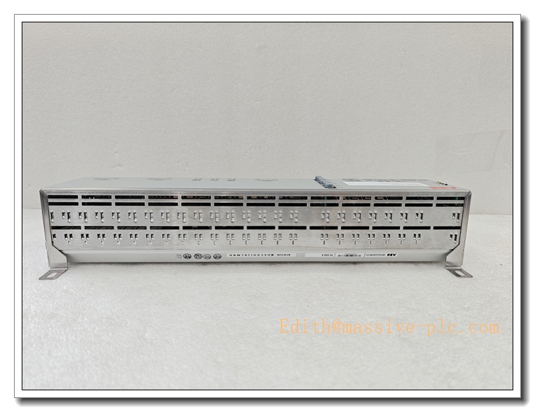
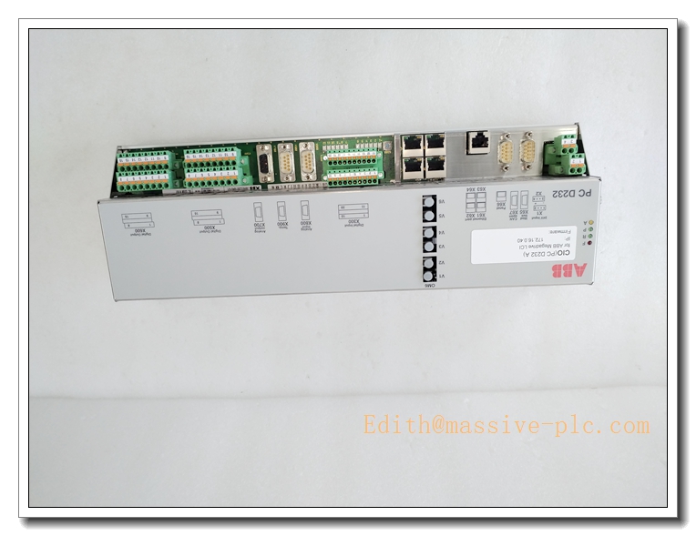
ABB PCD232A (3BHE022293R0101) Excitation Control Module for AC 800M Generator Excitation System
Core Product Introduction
PCD232A, part number 3BHE022293R0101, is an original ABB high-performance excitation control module belonging to the AC 800M DCS ecosystem, engineered for synchronous generator excitation regulation. It executes core Automatic Voltage Regulator (AVR) algorithms, field current closed-loop control, multi-limit supervision and thyristor firing pulse generation.
The module receives voltage and current sampled signals from dedicated phase interface boards, computes the required excitation output, and drives the power thyristor rectifier unit. Integrated comprehensive hardware and software self-diagnosis continuously monitors module health, channel integrity and pulse status, and transmits alarms, real-time operating data and event logs to the AC800M main controller through the rack backplane bus. Featuring high galvanic isolation between low-voltage control logic and high-energy pulse output circuits, the PCD232A provides robust protection against power plant surges, ground loops and heavy electromagnetic interference for long-term uninterrupted generator excitation operation.
PCD232A 3BHE022293R0101
Main Technical Specifications
Electrical Parameters
- Part Number: 3BHE022293R0101
- Designation: PCD232A
- Manufacturer: ABB
- Supply Voltage: 24 VDC (19.2–30 VDC, ±20% tolerance)
- Typical Power Consumption: ≤13 W
- Backplane Bus: AC 800M internal rack bus
- Core Control Function: AVR + field current closed-loop regulation
- Signal Input: Multi-channel VT/CT analog measurements
- Output: Firing pulses for excitation thyristor bridge
- Galvanic Isolation: Between control logic and pulse power interface
- Sampling Accuracy: ±0.2% FS
- Response Speed: Fast loop response for transient voltage correction
Environmental & Mechanical
- Operating Temperature: -25°C ~ +70°C
- Storage Temperature: -40°C ~ +85°C
- Relative Humidity: 5%–95% RH, non-condensing
- Protection Rating: IP20 (installation inside closed control cabinet only)
- Mounting: ABB standard rack plug-in module
- Weight: Approx. 250 g
- Vibration Standard: IEC 60068-2-6
- EMC Compliance: IEC 61000 series for power generation applications
Functional Features
- Full AVR control algorithm for synchronous generators
- Closed-loop field current regulation
- Multi-limit protection: overexcitation, underexcitation, V/Hz, reactive power & power factor limits
- Thyristor firing pulse generation and pulse monitoring
- Comprehensive onboard self-diagnostics & fault alarming
- Event logging for disturbance and fault sequence recording
- Hot-swap capable (subject to system configuration & site safety rules)
- Parameter configuration via Control Builder M
Recommended Models of the Same Series
All modules below fit the AC800M rack platform for generator excitation & power control systems:
- PCD231B 3BHE025541R0101: Standard excitation control module, widely used for conventional thermal and hydro generator AVR.
- PCD230B 3BHE024575R0101: Entry-level exciter controller for small-to-medium synchronous generators with basic limit functions.
- XVC772A102 3BHE032285R0102: Phase interface sampling board; paired with PCD232A to collect VT/CT phase voltage & current signals.
- PCD510A 3BHE005681R0101: Turbine governor high-speed control board for prime mover speed regulation.
PCD232A 3BHE022293R0101
Professional Quality Control Test Standard Operating Procedures (SOP)
5.1 Incoming Material Inspection
All semiconductors, precision resistors, isolation components and PCB substrates comply with ABB power-grade component specifications. Critical components are batch-sampled for temperature cycling, insulation and surge testing. Non-conforming materials are rejected and prohibited from entering assembly.
5.2 SMT Assembly and AOI Inspection
After surface mount soldering, automatic optical inspection (AOI) checks solder joints, component polarity and placement accuracy. Detected soldering defects are fully reworked before power-on functional testing.
5.3 Functional Bench Test
Each module is tested on dedicated ABB excitation test bench. Technicians validate AVR regulation performance, firing pulse generation, all limit logic, backplane communication and diagnostic alarm functions. Every control loop must meet accuracy and dynamic response specifications.
5.4 Hipot & Isolation Test
High voltage withstand test is applied to verify insulation integrity between low-voltage control circuits and high-energy pulse interfaces. No dielectric breakdown or excessive leakage current is permitted.
5.5 Thermal Aging Test
48-hour continuous powered aging under temperature cycling. Signal stability, pulse quality and bus communication performance are logged continuously to screen early-life failures.
5.6 Final QC & Traceability
Full retest of all functions, laser marking of serial and part numbers. Each unit gets unique traceability record and factory test certificate. Products comply with CE, UL and ISO9001 quality management system.
New Module Installation Guidelines
Pre-Installation Preparation
- Isolate and cut off the whole DCS rack power supply and execute lockout-tagout procedure to prevent accidental energization.
- Verify part number / 3BHE022293R0101 matches project BOM. Inspect PCB for shipping damage, bent pins or cracked components.
- Prepare ESD wristband and anti-static mat. Sensitive semiconductors on the PCB can suffer permanent damage from electrostatic discharge.
- Inspect rack slot and backplane connector for dirt, oxidation or deformed pins.
Installation Steps
- Wear ESD protection before handling the module. Hold only the front panel and board edges; never touch PCB traces or soldered components.
- Align module with rack guide rails and slide gently into the assigned slot. Push firmly until backplane connector is fully seated.
- Tighten front panel locking screws to secure module in rack.
- Wire external pulse and measurement circuits strictly following ABB schematic drawings. Torque terminals to specified value to avoid loose contacts or short circuits.
Post-Installation Commissioning
- Double-check all wiring; confirm CT/VT polarity and pulse cable connections are correct.
- Restore rack power gradually. Observe LED indicators: power LED steady ON, status LED without fault alarm.
- Launch Control Builder M engineering software, download excitation application parameters, verify sampled signal readings and control loop status.
- Perform static tests for AVR and all limit functions, check firing pulse output quality. Run a 30-minute continuous stability test before generator on-line commissioning.
PCD232A 3BHE022293R0101
Application Scenarios & Product Features
Main Application Scenarios
- Thermal power plant synchronous generator excitation control
- Hydropower station AVR systems
- Captive power plant generator voltage regulation
- Combined-cycle power generation units
- Large synchronous motor excitation control
Core Features
- Dedicated high-performance AVR algorithm for synchronous generators
- Integrated comprehensive excitation limit and protection functions
- High-speed thyristor firing pulse generation and monitoring
- Galvanic isolation protects DCS controller from power circuit transients
- Built-in full self-diagnostics for fast fault localisation
- Standard ABB plug-in rack design for simple maintenance and replacement
- Native integration with AC800M & Control Builder M
- Rugged hardware designed for power plant vibration and high EMC noise environments
Frequently Asked Questions (FAQ)
Q1: Power LED remains off after rack power-up? A1: Check rack backplane 24VDC supply, slot connector contact and module seating. Check for ESD damage occurred during handling. If supply is normal and indicator still off, the module has hardware failure and needs replacement.
A2: Verify CT/VT wiring polarity and sampling signal quality. Check excitation limit parameter settings inside Control Builder M and tune AVR PID parameters. If sampling signals are abnormal, inspect the paired phase sampling board.
Q3: Module reports communication timeout to AC800M controller? A3: Confirm the module is fully inserted into backplane. Validate hardware configuration in Control Builder M. Inspect backplane bus health and neighbouring modules. Restart the controller to reload hardware configuration.
A4: No. It adopts the dedicated AC800M internal rack bus and cannot operate on third-party racks or other control platforms.
A5: Hardware supports hot swap, but strict site safety procedures must be followed. Hot swapping while excitation power circuits are live is strictly prohibited.
Q6: What maintenance cycle is recommended? A6: Visual inspection of PCB and terminals every 6 months for dusty power plant environments. Full control loop calibration and parameter backup once per year. Avoid condensation and mechanical shock.


 Start Chat




