
Description
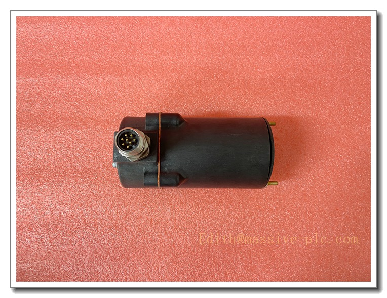
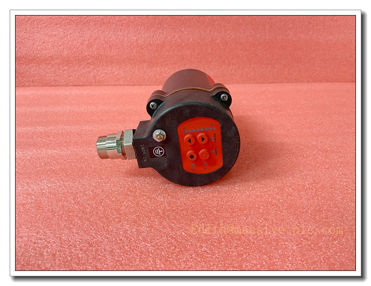
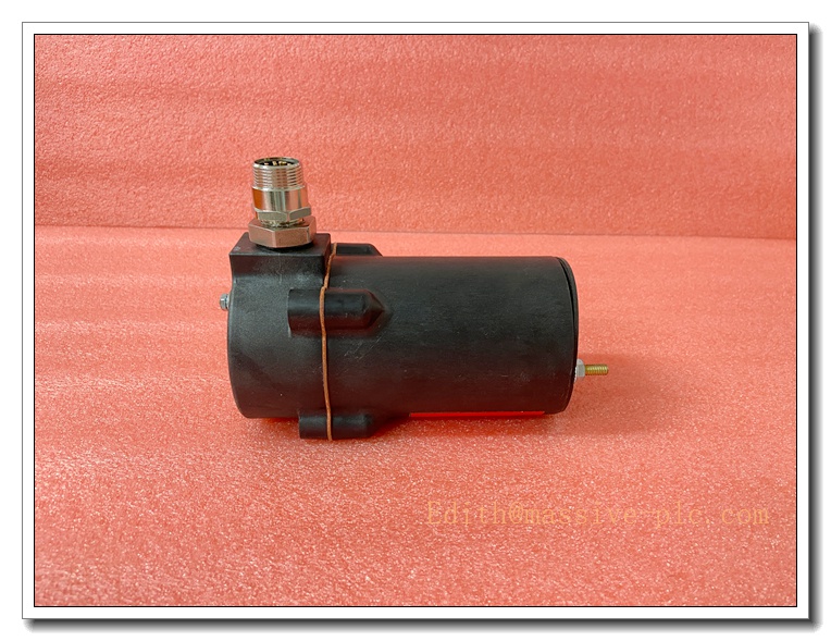
85UVF1-1QDK3 Fireye Phoenix UV Flame Scanner with K3 Filter, 24VDC Integrated Flame Detector, 4‑20mA & Modbus Output for Gas / Light Oil Burner in High‑Soot Furnace
Product Application
85UVF1‑1QDK3 belongs to Fireye Phoenix 85UVF series microprocessor UV flame detector, it is the K3 filter version of 85UVF1‑1QD. The added K3 optical filter suppresses interference signal caused by heavy soot, smoke and hot furnace background radiation. Integrated design: flame amplifier, signal processing board and output relays are all built inside scanner housing, no separate flame amplifier required. Widely applied to industrial boilers, waste incinerators, process heaters with heavy flue soot, furnaces with high background radiation. Applicable fuels: natural gas, propane, light fuel oil. It has strong cross‑flame discrimination capability in multi‑burner furnaces. Equipped with full electronic self‑diagnosis, internal dual relays directly output flame‑on and fault alarm signal to BMS, PLC or DCS. Suitable for Class I Div 2 / Zone 2 hazardous areas.
85UVF1-1QDK3
Product Specifications
- Part Number: 85UVF1‑1QDK3
- Brand: Fireye (USA)
- Series: Phoenix 85UVF Series 2
- Detection Type: Ultraviolet (UV) flame sensor + K3 optical filter
- Power Supply: 24 VDC ±10%
- Max Power Consumption: 3.5 W
- Electrical Interface: 8‑pin QD quick‑disconnect connector
- Analog Output: 4‑20 mA flame strength signal (sink / source configurable)
- Relay Output: Dual SPDT relays: Flame ON relay + Fault alarm relay, contact rating 5A @250VAC
- Flame Failure Response Time: Adjustable 1~6 seconds, factory default 3s
- Communication: RS‑485 Modbus RTU for remote parameter setting & flame signal reading
- Housing: Die‑cast aluminum, NEMA 4 / 4X (IP66)
- Sight Pipe Connection: 1‑1/2” NPT or 1‑1/2” BSP thread
- Purge Air Port: 3/8‑18 NPT / 3/8‑19 BSP for cooling & lens soot purge
- Operating Temp (Electronics): -40 ℃ ~ +65 ℃
- Lens Face Continuous Temperature: Max +121 ℃
- Certification: FM, UL/cUL, CE, ATEX, SIL3 capable
- Product Status: Active spare part for harsh combustion environment
Core Technical Parameters
- Detection Principle: Detect flame modulation flicker amplitude, automatic gain & flame threshold self‑learning
- Special Feature: K3 filter cuts off infrared and hot blackbody radiation interference, greatly improves signal‑noise ratio for smoky furnace
- Self‑Check: Full electronic self‑diagnosis for UV sensor, circuit and relay health, no mechanical shutter
- Flame Discrimination: Optimized for high‑soot working condition to distinguish target burner flame from background noise
- Compatibility: Directly connects to burner management system, PLC, DCS without external flame amplifier
- Weight: Approx. 1.3 kg
Recommended Matching Spare Parts & Accessories (8 Items)
- 59‑546‑X QD quick‑disconnect extension cable (different length options)
- 35‑318‑1 / ‑2 mounting flange
- Purge air fitting, pressure regulator & air filter for scanner cooling
- Burner sighting pipe assembly
- Shielded flame cable for Modbus RS485 communication
- Gas safety shut‑off solenoid valve
- Burner BMS / PLC burner control system
- Fireye configuration software for scanner parameter setup
Product Features
✅ Built‑in K3 Optical Filter for Heavy‑Soot Furnace K3 filter suppresses hot furnace infrared radiation and smoke interference, prevents false flame loss or false flame alarm in smoky combustion chamber.
✅ All‑in‑one Integrated Design Built‑in microprocessor, flame amplifier and dual output relays. Eliminates separate flame amplifier cabinet, reduces wiring cost and installation space.
✅ Automatic Flame Threshold Learning During commissioning, scanner automatically samples normal flame flicker signal, stores flame ON / OFF threshold and selects optimum gain, simplifies site calibration.
✅ 4‑20mA Flame Strength + Modbus Communication Real‑time flame intensity analog output; RS485 Modbus supports remote monitoring, parameter modification and fault diagnosis from DCS.
✅ QD Quick‑Disconnect Plug 8‑pin quick disconnect connector, convenient for scanner removal during maintenance without re‑terminating field cables.
✅ Hazardous Area & High SIL Capability Suitable for Zone 2 / Class I Div 2 hazardous locations; design meets SIL3 requirement for safety instrumented combustion system.
✅ Robust Enclosure with Purge Air Interface NEMA4X aluminum housing, dedicated purge air port to cool scanner and prevent soot deposition on quartz lens.
Installation Guidelines
- Mount 85UVF1‑1QDK3 onto burner sight pipe via 1‑1/2 inch thread, align optical axis to the flame root of target burner.
- Connect dry, clean instrument purge cooling air to 3/8” port, maintain proper airflow to keep lens clean and scanner temperature within limit.
- Wire power, relay signal and Modbus communication via 59‑546 series 8‑pin QD cable to BMS / DCS cabinet.
- Complete interlock wiring between Flame‑Off relay and fuel safety shut‑off valve.
- Power on scanner, enter teach‑in calibration mode to capture normal flame flicker signature under actual soot condition.
- Adjust flame failure response time according to burner safety requirement (1~6s).
- Perform flame loss test: cut off fuel supply and verify scanner triggers flame‑out relay action.
- Lock mounting thread and tighten housing cover to guarantee enclosure sealing.
85UVF1-1QDK3
Maintenance Instructions
Daily Maintenance Check flame intensity value on DCS / local indicator. Verify continuous purge air supply. Inspect quartz lens for heavy soot accumulation. Check housing seal integrity.
Periodic Maintenance (Every 6–12 months) Clean quartz lens surface soot. Run scanner self‑diagnostic function via Modbus. Inspect QD connector pin condition and cable tightness. Re‑run flame teach‑in after burner overhaul or obvious flue soot change.
Fault Maintenance
- Fault relay alarm: Execute scanner self‑diagnosis to confirm sensor / circuit failure, replace scanner if hardware fault confirmed.
- Frequent flame loss alarm: Clean lens soot, check purge air flow, re‑teach flame signature, confirm K3 filter is not scratched.
- False flame signal: Check cross‑fire interference from adjacent burners, adjust scanner viewing angle.
- Do not disassemble internal PCB assembly inside housing.
Long‑Term Operation Tips Keep stable, dry purge cooling air supply. Avoid direct furnace high‑temperature radiation to scanner body. Stock spare QD extension cable for quick replacement.
Brand Same‑Series Models (6 Models)
- 85UVF1‑1QDK3 – UV scanner with K3 filter for heavy soot environment, QD connector (Target Model)
- 85UVF1‑1QD – Standard UV scanner without K3 filter
- 85UVF4‑1QD – High sensitivity UV variant
- 85IRF1‑1QD – Infrared flame scanner for heavy oil / solid fuel
- 45UV5‑1101 – Older generation mechanical shutter self‑check UV scanner
- 25SU5 – Fireye standalone flame safeguard controller



 Start Chat




