
Description
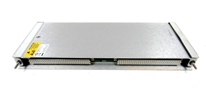
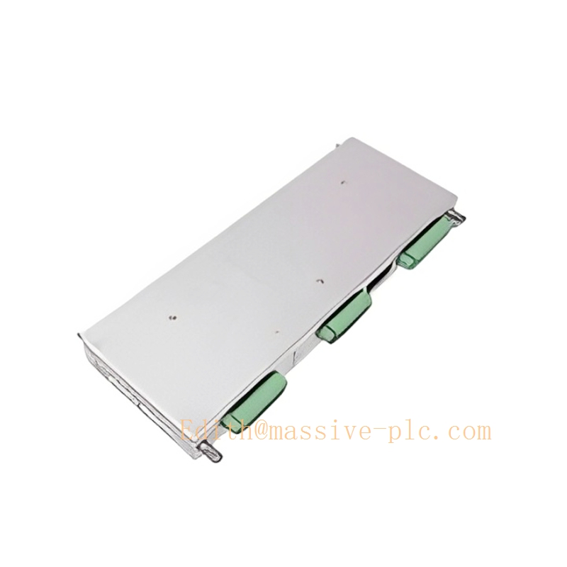
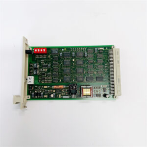
3500/45 I/O Module P/N 139567‑01
350045 135145-01
Product Introduction
The 139567‑01 is an AC‑LVDT Position I/O Module (external termination) designed for pairing with the Bently Nevada 3500/45 Position Monitor base board (176449‑04) within the 3500 machinery protection system. It is dedicated interface hardware for AC‑excited LVDT position transducers, providing signal conditioning, excitation drive and field wiring terminals for turbine differential expansion, case expansion and valve‑position measurement applications.
Distinguished from 139554‑01 (AC‑LVDT I/O with internal termination), 139567‑01 adopts external termination design: field sensor cables land onto separate external terminal blocks instead of connectors mounted directly on the I/O module front‑plate. This layout simplifies cabinet wiring layout, supports remote terminal arrangement and facilitates hot‑swap of the 3500/45 monitor without disturbing field sensor cabling.
Typical deployment: steam turbine, gas turbine and large compressor TSI systems, processing AC‑LVDT feedback for casing thermal growth, rotor differential expansion and control‑valve stem position. It works in channel‑pair mode together with the main 3500/45 monitor board to deliver alarm, trip and 4‑20 mA analog output for DCS interlock.
Technical Specification
- Transducer Compatibility
- Optimized for AC‑LVDT position transducers; supplies AC excitation drive for LVDT coils
- External termination interface; sensor wiring connects to off‑board terminal assemblies
- Matches 3500/45 monitor 4‑channel pair‑wise measurement architecture (Ch1‑2 / Ch3‑4)
- Electrical Parameters
- Excitation: AC drive for LVDT primary winding (frequency & amplitude controlled by 3500/45 main monitor)
- Input signal: secondary differential feedback signal from AC‑LVDT
- Power consumption: typical 8.5 W when 3500/45 uses AC‑LVDT I/O set (main board + 139567‑01 I/O)
- Backplane bus connection: plugs into 3500/45 monitor front‑slot as daughter I/O assembly
- Measurement Functions Supported (configured in 3500 software)
- Differential Expansion (single‑ramp / dual‑ramp / complementary)
- Case Expansion
- Valve Position
- Axial thrust position (if AC‑LVDT type thrust sensor is applied)
- Environment & Mechanical
- Operating temperature: 0 °C ~ +60 °C
- Storage temperature: −40 °C ~ +85 °C
- Form factor: daughter‑card I/O module for 3500/45 position monitor; rack‑mount inside 3500 system cabinet
- Origin: USA
- System Interface
- Transmits conditioned LVDT signals to 3500/45 main monitor for engineering‑unit conversion, alarm‑trip logic
- Monitor main board provides relay alarm/trip outputs and 4‑20 mA analog outputs to plant control system
Key difference reference |Part Number|Type|Termination Style| |—|—|—| |139554‑01|AC‑LVDT I/O Module|Internal termination (wires plug directly to I/O module front‑plate)| |139567‑01|AC‑LVDT I/O Module|External termination (field cables connect to separate external terminal blocks)|
Adaptive Quality Assurance & Test Protocol
Adaptive Quality Assurance
- Power‑on POST Self‑Test Upon rack power‑up, 3500/45 main monitor executes full diagnostic coverage on the 139567‑01 I/O daughter module: excitation drive circuit health, input differential signal path, inter‑board communication link between main monitor and I/O card. Fault conditions are flagged via module front‑panel OK LED and system event log.
- Runtime Adaptive Background Diagnostics During online operation, non‑intrusive background tests run adaptively. Diagnostic sampling frequency increases when LVDT signal fluctuation or noise is detected; test overhead is reduced under stable measurement status to avoid interference with protection functions. Continuously monitor LVDT coil open‑circuit, short‑circuit and excitation‑loop failure; report sensor/IO faults without spurious trip triggering.
- Channel‑pair health supervision Each channel pair (1‑2, 3‑4) of 139567‑01 is supervised independently. Fault on one channel pair will not impair measurement performance of the other pair.
Test Protocol
- Static Calibration Test Inject simulated AC‑LVDT differential signals via external termination terminals; verify reading accuracy inside 3500 configuration software, validate full‑scale scaling and corresponding 4‑20 mA output.
- Excitation Loop Test Measure AC excitation output delivered by 139567‑01 to LVDT primary winding; confirm amplitude and frequency match configuration parameters.
- Alarm & Trip Threshold Validation Apply simulated position signals crossing alarm / trip setpoints; verify 3500/45 main monitor correctly assert status, relay action and system event logging.
- Inter‑board Communication Test Verify reliable data exchange between 139567‑01 I/O daughter‑card and 3500/45 main monitor board; test configuration download, real‑time data upload and fault‑reporting pathways.
- Factory environmental stress screening Temperature cycling, power‑supply variation tests performed at factory production phase to validate long‑term robustness under industrial cabinet conditions.
Important note: Adaptive background diagnostics never override hard‑wired trip logic; protection response maintains highest execution priority.
Field Engineer Technical Instruction
Installation
- Power down target 3500/45 monitor slot before servicing. Insert 139567‑01 AC‑LVDT external‑termination I/O daughter‑card into the dedicated front I/O connector of the 3500/45 main monitor (176449‑04). Secure module latches.
- Field AC‑LVDT sensor cables do not connect directly to 139567‑01; route all sensor wiring to the matching external termination terminal hardware. Follow vendor drawing for shield grounding practice; separate low‑level LVDT signal cables from high‑power AC/DC power cables to minimize electromagnetic interference.
- Confirm complete hardware set: 3500/45 main monitor + 139567‑01 I/O module + external termination assembly; mismatch will cause measurement failure.
Configuration
- Launch 3500 Rack Configuration Software, assign I/O hardware type as 139567‑01 AC‑LVDT External Termination.
- Select measurement function per channel‑pair: differential expansion, case expansion or valve position; set LVDT characteristic parameters, full‑scale measuring range, alarm / trip thresholds and time‑delay.
- Download configuration to 3500 rack. After download, perform static signal injection test via external terminals to validate channel response.
Commissioning
- On‑site LVDT mechanical zero‑point calibration; verify engineering‑unit readings match mechanical reference position.
- Simulate alarm and trip conditions, check downstream plant interlock logic.
- Observe 3500/45 front‑panel LED status: Green=OK; Yellow=Alarm; Red=Trip / Hardware Fault. I/O‑related faults will be logged in system event viewer.
Troubleshooting
- LVDT signal loss / channel fault: Inspect external termination block connections, check LVDT coil for open‑short, verify excitation circuit.
- Reading drift or noise: Check cable shielding & grounding, inspect external terminal block loose terminals, confirm no high‑voltage cable crosstalk.
- I/O module fault reported: Perform rack slot power‑cycle; if fault persists, replace 139567‑01 daughter I/O module and reload rack configuration.
Maintenance
- 139567‑01 is a non‑repairable daughter‑card assembly; no on‑board component repair permitted. Replace whole unit upon confirmed failure.
- During unit shutdown windows, perform periodic calibration check by injecting simulated AC‑LVDT signals at external termination terminals.
Related Series Model List
3500/45 Position Monitor main board
- 176449‑04 3500/45 Position Monitor Main Module
AC‑LVDT I/O daughter‑cards
- 139554‑01 AC‑LVDT I/O Module, internal termination
- 139567‑01 AC‑LVDT I/O Module, external termination
Proximitor / Position I/O
- 135137‑01 Position I/O Module, internal termination
- 135145‑01 Position I/O Module, external termination
Rotary Potentiometer I/O
- 139978‑01 Rotary Potentiometer I/O, internal termination
- 139991‑01 Rotary Potentiometer I/O, external termination
Other 3500 family monitor modules
- 3500/40 Proximity Monitor
- 3500/42 Position Monitor
- 3500/46 Differential Expansion Monitor
- 3500/50 Tachometer Module
- 3500/53 Relay Module
- 3500/60 Temperature Monitor
- 3500/62 Temperature Monitor


 Start Chat




