
Description
3500/45 P/N 128015‑06
Product Introduction
The 128015‑06 is a Position External Termination Block (terminal‑strip style) for the Bently Nevada 3500/45 Position Monitor system. It works together with the 135145‑01 Position I/O daughter‑card (external termination type) and the 3500/45 main monitor board (176449‑04).
This external termination block serves as the intermediate wiring interface for Proximitor proximity probes, Rotary Position Transducers (RPT), and DC‑LVDT sensor signals. Field sensor cables land onto screw‑type terminal strips on 128015‑06, and short jumper cables connect this block to the 135145‑01 I/O module.
This external‑termination architecture enables hot‑swap replacement of the 3500/45 I/O daughter‑card without disconnecting field sensor wiring. It is widely deployed in steam‑turbine TSI systems for axial thrust position, DC‑LVDT case expansion and valve‑position measurement. It is not a monitor main board or I/O daughter‑card, but a wiring terminal accessory for external‑termination hardware sets。
Typical complete hardware set:
3500/45 Main Monitor (176449‑04) + Position I/O Module 135145‑01 (External Termination) + External Termination Block 128015‑06
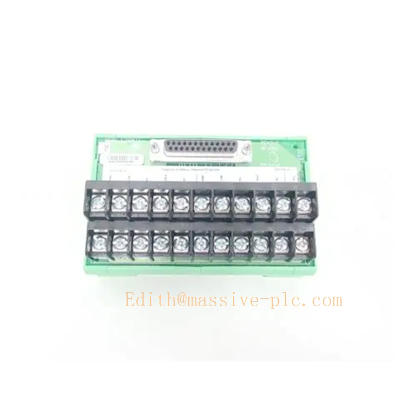
350045 128015-06
Technical Specification
- Supported Transducer Types
- Proximitor eddy‑current proximity sensor (3300XL series)
- Rotary Position Transducer (RPT)
- DC‑LVDT position transducers
Not compatible with AC‑LVDT sensors; AC‑LVDT external termination uses 141208‑01 block instead
- Mechanical & Wiring
- Connection: Screw terminal‑strip field wiring; dedicated ribbon‑cable interface for mating with 135145‑01 I/O daughter‑card
- Channel coverage: 4 measurement channels for 3500/45 position monitor channel‑pair architecture (Ch1‑2 / Ch3‑4)
- Mounting: Standard DIN‑rail cabinet mounting inside instrument cabinet
- Form factor: Passive termination assembly, no active electronic measurement circuits
- Environmental Rating
- Operating temperature: 0 °C ~ +60 °C
- Storage temperature: −40 °C ~ +85 °C
- Designed for industrial control cabinet installation, petrochemical & power‑plant TSI environment
- System Compatibility
- Exclusive match: 3500/45 with 135145‑01 external‑termination Position I/O module
- Cannot pair with internal‑termination I/O cards (135137‑01, 139554‑01)
- Does not work with AC‑LVDT I/O 139567‑01
Hardware matching reference table |Part Number|Description|Mating I/O Card|Sensor Type| |—|—|—|—| |128015‑06|Position External Termination Block (terminal strip)|135145‑01|Proximitor / RPT / DC‑LVDT| |141208‑01|AC‑LVDT External Termination Block|139567‑01|AC‑LVDT| |125808‑06|Position‑Prox/DC LVDT‑Euro block|135145‑01|Proximitor / RPT / DC‑LVDT (Euro connector)|
Adaptive Quality Assurance & Test Protocol
Adaptive Quality Assurance
Since 128015‑06 is a passive wiring termination block without embedded microprocessor or self‑diagnostic circuits, adaptive QA functions are implemented on paired 3500/45 main monitor and 135145‑01 I/O module.
- Power‑on POST Self‑Test The 3500/45 monitor executes channel loop diagnostics upon rack power‑up. Open‑circuit, short‑circuit or high‑resistance connection faults introduced by loose terminals on 128015‑06 will be detected and reported as sensor‑path faults on monitor LED and system event log.
- Runtime Adaptive Background Diagnostics During online operation, the 135145‑01 I/O module continuously monitors signal loop health via 128015‑06 termination points. Increased noise or intermittent signal caused by poor terminal contact will trigger channel fault alerts, without generating spurious machine trip actions. Diagnostic sampling frequency rises when signal instability is detected.
- Channel‑pair Independent Supervision Fault on one channel pair routed through 128015‑06 will not affect the other channel‑pair measurement path.
Test Protocol
- Loop Continuity Test Conduct continuity check for each sensor path from 128015‑06 terminal strip to 135145‑01 I/O module by injecting simulated proximity / DC‑LVDT signals at field‑side terminals. Verify signal arrives correctly at monitor input channels.
- Contact Resistance Validation Check for excessive contact resistance at screw terminals; confirm no intermittent connection under cabinet vibration simulation.
- Full‑scale Calibration Test Inject full‑range simulated transducer signals on 128015‑06 field terminals, verify engineering‑unit reading accuracy, alarm & trip response and 4‑20 mA analog output performance of the complete 3500/45 system.
- System Communication & Fault Reporting Test Manually create open‑circuit / short‑circuit fault on 128015‑06 terminals; confirm fault events are correctly logged within 3500 system event viewer.
Important note: 128015‑06 itself contains no active test or protection logic. All protection functions reside on 3500/45 main monitor and its I/O daughter‑card.
Field Engineer Technical Instruction
Installation
- Mount 128015‑06 termination block on standard DIN‑rail inside instrument cabinet. Keep physical separation from high‑power AC/DC cables to reduce electromagnetic interference.
- Route field Proximitor / RPT / DC‑LVDT sensor cables to screw‑type terminals of 128015‑06; strictly follow drawing for shield grounding scheme.
- Use designated short ribbon jumper cable to connect 128015‑06 to 135145‑01 external‑termination I/O daughter‑card plugged into 3500/45 monitor. Confirm secure locking of both ends of jumper cable.
- Verify complete hardware set: 3500/45 main board +135145‑01 I/O +128015‑06 termination block. Mismatched hardware will produce measurement failure.
Configuration
- In 3500 Rack Configuration Software, select I/O hardware type as 135145‑01 Position I/O External Termination.
- Assign measurement function per channel‑pair: axial thrust position, DC‑LVDT case expansion, valve position etc. Set transducer sensitivity, full‑scale range, alarm / trip thresholds and time‑delay parameters.
- Download configuration to rack. Perform signal injection test at 128015‑06 field terminals to validate channel response.
Commissioning
- Complete field transducer mechanical zero‑point calibration; verify monitor engineering‑unit readings match mechanical reference position.
- Simulate alarm and trip threshold conditions, validate plant interlock downstream logic.
- Observe 3500/45 front‑panel LED status: Green=OK; Yellow=Alarm; Red=Trip / Hardware Fault. Poor terminal contact on 128015‑06 will trigger channel fault events in system log.
Troubleshooting
- Sensor channel fault / signal loss: Inspect screw terminals on 128015‑06 for loose wiring, check jumper cable connection between termination block and 135145‑01 I/O module; inspect transducer cable for open‑short.
- Reading drift / noisy signal: Re‑check shield grounding at 128015‑06 terminals; separate low‑level sensor wiring from high‑voltage power cables; retighten all screw terminals.
- Intermittent channel fault: Re‑torque terminal screws on 128015‑06; inspect jumper cable for pin damage.
Maintenance
- 128015‑06 is passive assembly; no internal component repair. Replace whole unit if terminal damage occurs.
- During unit shutdown, retighten all field‑wiring screw terminals and perform signal injection test at block terminals for periodic health verification.
Related Series Model List(Associated 3500/45 Hardware)
3500/45 Main Monitor
- 176449‑04 3500/45 Position Monitor Main Board
Position I/O Daughter‑Cards
- 135137‑01 Position I/O Module, internal termination (Proximitor / RPT / DC‑LVDT)
- 135145‑01 Position I/O Module, external termination (Proximitor / RPT / DC‑LVDT)
- 139554‑01 AC‑LVDT I/O Module, internal termination
- 139567‑01 AC‑LVDT I/O Module, external termination
External Termination Blocks
- 128015‑06 Position External Termination Block (terminal‑strip, Prox/RPT/DC‑LVDT)
- 125808‑06 Position External Termination Block (Euro‑connector, Prox/RPT/DC‑LVDT)
- 141208‑01 AC‑LVDT External Termination Block
Other 3500 series monitor modules
- 3500/40 Proximity Monitor
- 3500/42 Position Monitor
- 3500/46 Differential Expansion Monitor
- 3500/50 Tachometer Module
- 3500/53 Relay Module
- 3500/60 Temperature Monitor
- 3500/62 Temperature Monitor



 Start Chat




