
Description
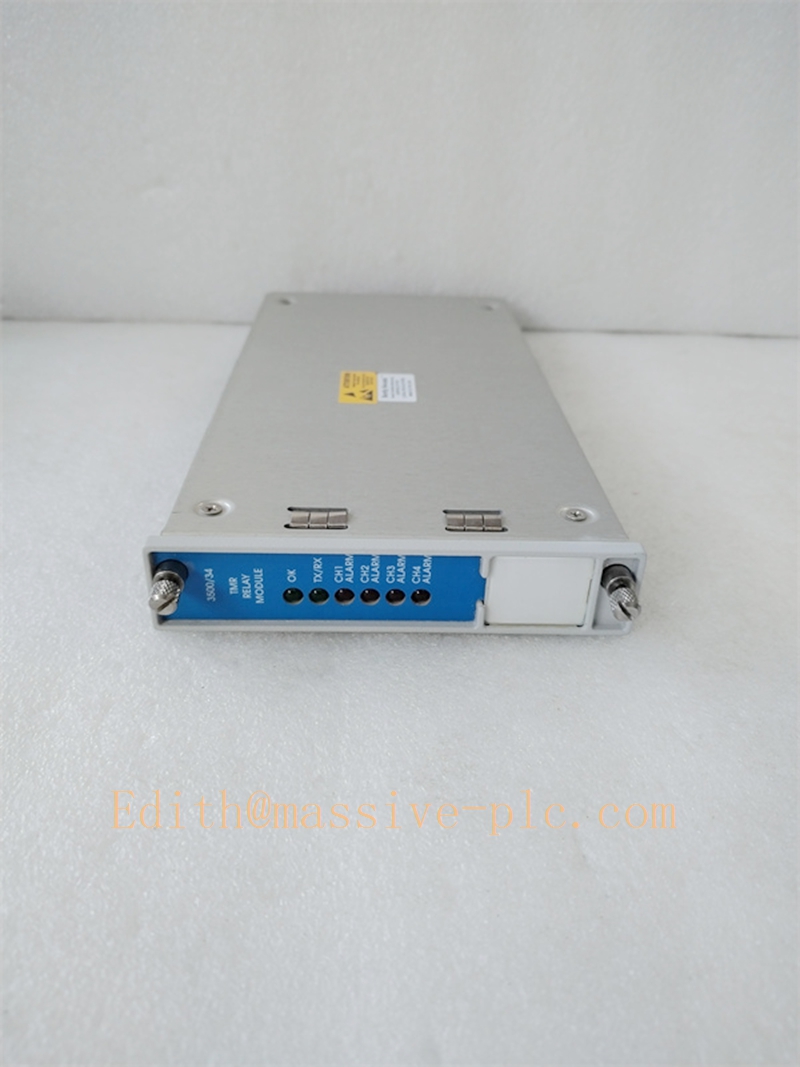
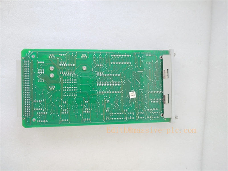
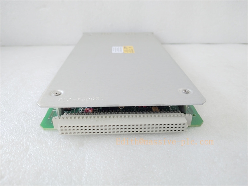
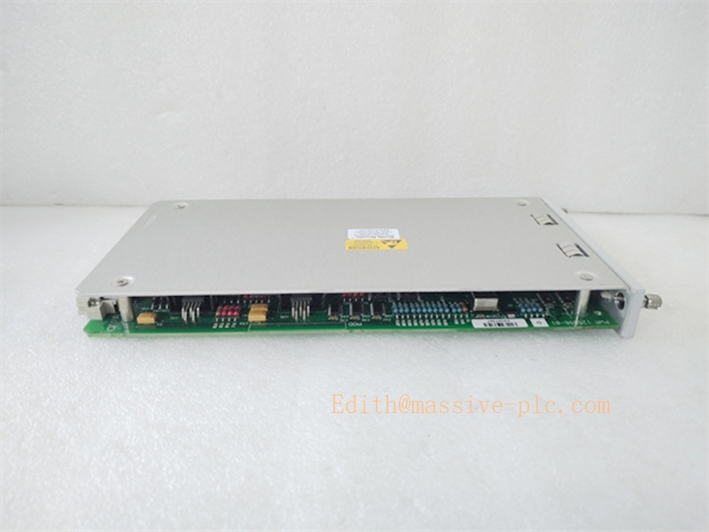
3500/34 (125696-01) Bently Nevada TMR Relay Output Module Full Specification
Product Description
The Bently Nevada 3500/34 with part number 125696-01 is a high-integrity TMR (Triple Modular Redundant) relay output module designed for the Bently Nevada 3500 machinery protection system. As a core safety-grade output component, it delivers fault-tolerant trip and alarm signal execution for critical rotating machinery. Adopting a strict 2-of-3 voting architecture, the module eliminates single-point failures within protection loops, providing reliable hard-wired relay outputs for interlocking with ESD, PLC, DCS and emergency shutdown systems.
Cooperating seamlessly with 3500 series vibration, position and temperature monitor modules, the 125696-01 variant converts system internal logic judgments into field-executable contact signals. Optimized for 24/7 continuous operation in power, petrochemical and heavy industrial environments, it complies with API 670 machinery protection standards and supports SIL-capable safety loop deployment, ensuring minimal false-trip rate and maximum equipment protection availability.
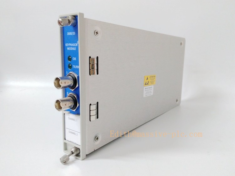
3500/34 125696-01
Core Technical Specifications
| Model Number | 3500/34, Part No. 125696-01 |
| Module Type | TMR Triple Modular Redundant Safety Relay Output Module |
| Output Channel Quantity | 4 independent configurable TMR relay output channels |
| Voting Logic | 2-of-3 fault-tolerant voting per channel, single-fail safe design |
| Contact Configuration | Software configurable Form A (NO) / Form B (NC) dry contacts |
| Contact Rating | Resistive load: 120 VAC / 30 VDC maximum, industrial safety interlock rating |
| Response & Delay | Fast relay actuation; user-programmable alarm/trip time delay |
| System Communication | 3500 rack backplane high-speed bus, fully synchronized with monitor modules |
| Diagnostic Capability | Full channel self-test, relay coil/continuity health monitoring, fault logging and reporting |
| Compliance & Safety | API 670 compliant, suitable for SIL-rated machinery safety protection loops |
| Power Source | Backplane-powered, compatible with 3500/15 redundant power supply system |
| Operating Temperature | 0 °C to +60 °C |
| Storage Temperature | -40 °C to +85 °C |
| Mounting Type | Standard 3500 series rack-mounted modular installation |
Key Features & Competitive Advantages
3.1 Core Features
- TMR Fault-Tolerant Safety Architecture: Each output channel adopts triple redundant circuit design with 2-of-3 voting logic. Single internal circuit or relay faults will not trigger false trips or cause protection failure, ensuring continuous safety loop availability.
- Multi-Functional Four-Channel Output: Supports independent configuration for warning alarms, danger trips, system fault indication and auxiliary equipment interlocks, enabling hierarchical and multi-scenario protection output management.
- Dual Contact Logic Flexibility: Freely switchable Form A normally-open and Form B normally-closed contact modes, perfectly adapting to diverse ESD interlock, alarm display and emergency shutdown loop designs.
- Full-Coverage Self-Diagnosis System: Real-time monitoring of relay coil status, contact integrity and channel circuit health. Automatically records and reports abnormal channels, eliminating hidden failure risks of protection loops.
- Precise System Synchronization: Maintains strict logic synchronization with all 3500 series monitoring modules, ensuring consistent fault judgment and instantaneous protection output execution.
- Enhanced Industrial EMC Design: Optimized electromagnetic interference resistance design, maintaining stable relay output without jitter or misoperation in high-noise industrial field environments.
3.2 Product Advantages
- Extremely Low False-Trip Rate: TMR voting mechanism effectively filters transient interference and sporadic system faults, avoiding unnecessary equipment shutdowns and improving overall production line operating efficiency.
- High Safety Integrity Level: Meets industrial heavy-duty machinery protection specifications, applicable to core key equipment scenarios that cannot tolerate protection failure or missed trips.
- Full System Compatibility: Plug-and-play compatible with all standard 3500 rack systems, requiring no chassis structure modification during equipment replacement, expansion and system upgrade.
- Simplified On-Site O&M: Centralizes all machine protection output signals on a single module, reducing on-site wiring complexity and lowering system debugging and daily maintenance costs.
- Superior Long-Term Stability: Adopts industrial-grade relay components and rigorous circuit design, supporting long-cycle uninterrupted operation under harsh industrial continuous working conditions.
Typical Application Fields
The 3500/34 125696-01 TMR relay module acts as the safety output execution core of the 3500 machinery protection system, widely deployed in high-reliability industrial safety monitoring scenarios:
- Power Generation Industry: Turbine, generator and large auxiliary fan vibration trip protection, bearing fault alarm and unit interlock control for thermal power and gas power plants.
- Petrochemical & Refinery Industry: Safety protection output for large centrifugal compressors, process pumps and high-speed rotating equipment, cooperating with factory ESD emergency shutdown systems.
- Oil & Gas Industry: Mechanical safety interlock and fault alarm output for onshore and offshore process rotating equipment.
- Metallurgy & Heavy Industry: Protection signal execution for large rolling mills, high-power fans and industrial transmission rotating equipment.
- SIL Safety Critical Projects: Specialized for safety-level monitoring systems requiring high fault tolerance, low false-trip and high operational reliability.
- Legacy System Retrofit & Spare Replacement: Standard compatible spare part for existing 3500 rack systems, ensuring consistent protection logic and stable system operation after module renewal.
Technical Pitfalls to Avoid
- Improper Voting & Delay Parameter Setup: Unreasonable channel voting parameters or protection delay settings may lead to delayed fault response or failed trip action, causing potential mechanical equipment damage.
- Reverse Contact Logic Configuration: Mixing up Form A and Form B contact modes will reverse alarm and trip logic, resulting in interlock failure or unplanned system shutdown.
- Overloaded Contact Operation: Exceeding the module’s rated contact voltage and current will cause relay contact ablation, adhesion and permanent failure, leading to protection loop paralysis.
- Disabled Regular Self-Diagnosis: Long-term deactivation of channel self-test functions will hide single-channel faults, gradually weakening TMR fault-tolerant performance and losing redundant protection capability.
- Unstable Backplane Power Supply: Fluctuating or substandard rack power supply will trigger module logic reset and intermittent relay misoperation, affecting system safety stability.
- Non-Standard Field Wiring & Grounding: Unseparated power and signal cables and non-standard shielding grounding will introduce strong EMI interference, causing accidental relay action.
- Mismatched Module Firmware Version: Inconsistent firmware versions between the 125696-01 relay module and front-end monitoring modules will cause logic synchronization errors and abnormal output signals.
Related Product Recommendations
- Bently Nevada 3500/33 Vibration Monitor Module: Matching front-end vibration and position acquisition module, providing accurate fault judgment signals for 3500/34 relay output execution.
- Bently Nevada 3500/20 Rack Interface Module: System core communication and logic scheduling unit, ensuring synchronous data interaction and coordinated operation of all rack modules.
- Bently Nevada 3500/15 Power Supply Module: Redundant power supply unit to provide stable and reliable backplane power for TMR relay output modules.
- 3300 Series Proximity & Velocity Sensors: Specialized field sensing sensors for machinery vibration and displacement monitoring, supporting full closed-loop protection system construction.
- Bently Nevada 3500 Configuration Software: Professional dedicated tool for relay channel logic configuration, delay parameter setting, self-test activation and system fault diagnosis.
- Safety Isolation Terminal Accessories: Auxiliary isolation components for external interlock loops, protecting module contacts and improving field anti-interference ability.
Installation Guidelines
- Standard Rack Installation: Install the module in a fully grounded standard 3500 industrial rack, placed in a temperature-controlled, dust-proof and dry electrical cabinet to avoid corrosive gas, excessive humidity and strong mechanical vibration.
- Reliable Backplane Connection: Ensure firm and tight card edge contact with the rack backplane; avoid loose insertion which may cause communication interruption and internal logic disorder.
- Standardized Field Wiring: Strictly distinguish Form A/Form B contact terminals during wiring; separate protection signal cables from high-voltage power cables and implement standard single-point shielding grounding.
- Reasonable Parameter Configuration: Set independent alarm/trip thresholds and delay parameters for each channel according to on-site equipment protection specifications, and match upper ESD and DCS interlock logic.
- Pre-Operation Functional Verification: Complete channel self-test, logic simulation and contact action inspection after installation to ensure all protection output functions are accurate and effective before formal system operation.
Daily Maintenance Guidelines
- Routine Status Inspection: Regularly check module operating indicators, relay channel working status and wiring tightness; clean module surface and terminal block dust quarterly to ensure unobstructed heat dissipation.
- Periodic System Self-Test: Trigger manual system self-diagnosis every six months to detect hidden faults in TMR channels and relay contacts in advance and eliminate potential risks.
- Regular Logic Calibration: Periodically verify the consistency between monitoring alarm logic and relay output actions to prevent parameter drift from causing protection deviation.
- External Loop Maintenance: Regularly inspect the insulation and aging status of external interlock loop cables, replace aging and damaged accessories in time to avoid contact failure and signal leakage.
- Spares Management & Maintenance: Store standby 125696-01 modules in constant-temperature and dry environment; perform regular power-on aging tests to ensure complete functional availability for emergency replacement.


 Start Chat




