
Description
3500/33 (149992-02) Bently Nevada 16-Channel Relay Output Module Full Specification
Product Description
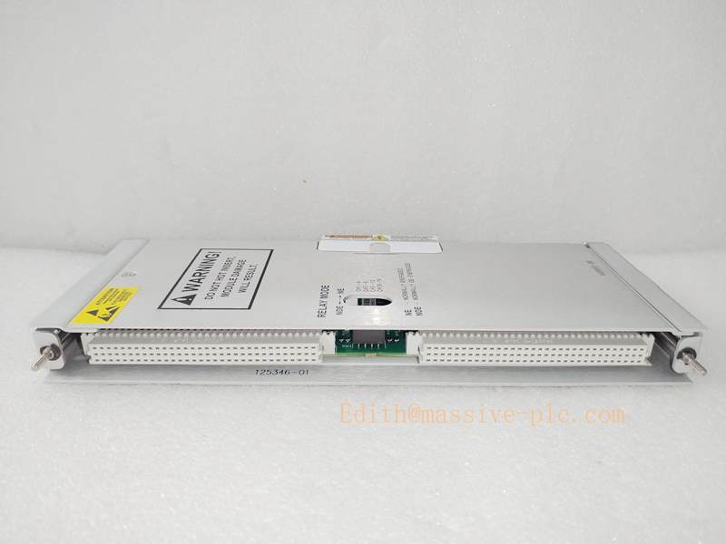
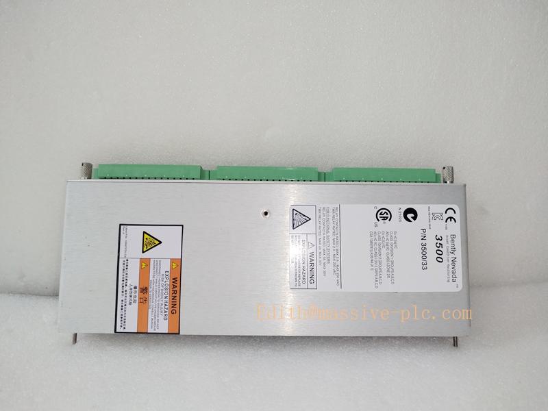
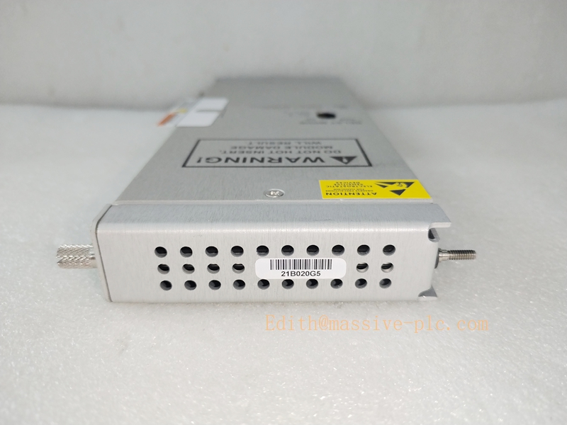
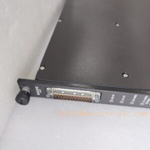
The Bently Nevada 3500/33 with part number 149992-02 is a high-density 16-channel relay output module designed for the 3500 machinery protection and condition monitoring system. As a core logic execution module, it receives alarm and trip judgment signals from monitor modules (such as 3500/40M, 3500/42M, 3500/50) and converts internal system logic status into hardwired relay contact outputs for external interlock, alarm indication and equipment trip control.
The 149992-02 revision features ATEX / IECEx / CSA Zone 2 hazardous area certification, industrial-grade fail-safe logic, and fully programmable channel voting strategies. With 16 independent SPDT relay channels integrated in a single slot, it maximizes rack density and simplifies field wiring. This module serves as the final execution unit for machinery safety protection loops, widely deployed on turbines, compressors, generators and other critical rotating equipment to realize reliable safety interlock and emergency shutdown logic.
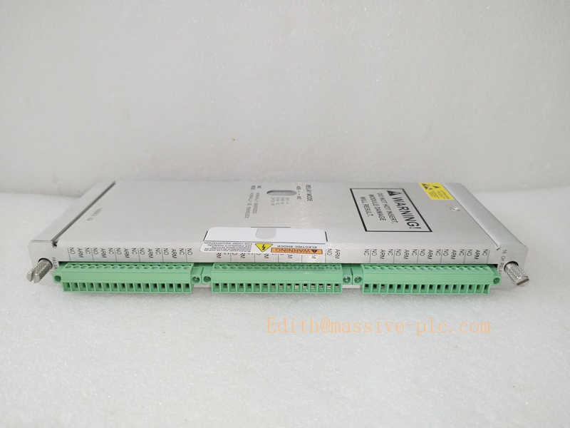
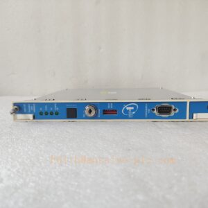
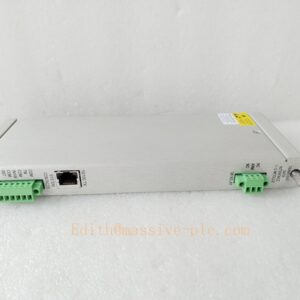
3500/33 149992-02
Core Technical Specifications
| Model Number | 3500/33, Part No. 149992-02 |
| Module Type | 16-Channel Programmable Relay Output Module |
| Relay Type | SPDT (Single-Pole Double-Throw), Fail-Safe configurable |
| Channel Quantity | 16 fully independent programmable relay output channels |
| Contact Rating | 10 A @ 250 VAC / 250 VDC resistive load |
| Typical Power Consumption | 5.8 W standard operating power |
| Operating Temperature | -30 °C to +65 °C industrial continuous range |
| Storage Temperature | -40 °C to +85 °C |
| Humidity Range | 5%–95% non-condensing |
| Certification Grade | ATEX / IECEx / CSA Class I Zone 2 hazardous area approval |
| Safety Rating | SIL 2 capable for machinery protection loop |
| Logic Mode | User-configurable latching/non-latching, voting, fail-safe energize/de-energize |
| System Compatibility | Full compatibility with all standard 3500 rack systems and configuration software |
| Installation Type | Standard 3500 series rack slot mounting |
Key Features & Competitive Advantages
3.1 Core Features
- High-Density 16-Channel Relay Output: Integrates 16 independent SPDT relay contacts in single-slot design, greatly reducing rack occupancy and field wiring complexity compared with traditional low-density relay modules.
- Fully Programmable Protection Logic: Each relay supports independent configuration of alarm/trip source, voting logic (1oo2, 2oo2, custom voting), latching mode and fail-safe direction, matching diverse machinery protection interlock strategies.
- Zone 2 Hazardous Area Certified: 149992-02 revision carries complete ATEX, IECEx and CSA Zone 2 certification, suitable for installation in onshore petrochemical, oil and gas and other explosive hazardous environments.
- Industrial Fail-Safe Mechanism: Supports de-energize-to-trip safety mode. In case of module power failure, rack fault or communication interruption, relays switch to predefined safe state to avoid protection failure.
- SIL 2 Functional Safety Compliance: Meets industrial SIL 2 safety integrity requirements for machinery protection loops, supporting formal safety instrumented system (SIS) deployment and audit.
- Comprehensive Self-Diagnosis: Real-time monitoring of module operating status, communication status and relay logic state, outputting fault indications for abnormal communication, power anomaly and module failure.
3.2 Product Advantages
- Maximized Cabinet Space Utilization: Single-slot 16-channel design replaces multiple low-density relay modules, effectively saving cabinet layout space and reducing overall system investment.
- Strong Environmental Adaptability: Wide temperature and non-condensing humidity tolerance plus Zone 2 hazardous area approval adapt to most complex industrial site conditions.
- Flexible and Accurate Logic Matching: Rich configurable logic modes support customized alarm classification, group voting and trip interlock, avoiding false trips and missed trips in unit protection.
- Excellent System Compatibility: Plug-and-play compatible with all generations of 3500 racks and monitor modules, suitable for new project construction, old system renovation and spare replacement.
- Low Operation and Maintenance Cost: Highly integrated design reduces wiring points and fault nodes, lowering daily inspection and troubleshooting workload.
Typical Application Fields
The 3500/33 149992-02 relay module is the standard safety execution unit for 3500 machinery protection systems, widely used in high-reliability industrial safety interlock scenarios:
- Thermal & Gas Power Generation: Turbine and generator vibration trip, thrust fault interlock, abnormal condition alarm output and auxiliary equipment linkage control.
- Petrochemical & Refinery Industry: Safety interlock and ESD auxiliary output for large centrifugal compressors, turbo pumps and high-speed process units in hazardous areas.
- Onshore & Offshore Oil and Gas Facilities: Zone 2 hazardous area compliant machinery protection signal execution and remote alarm transmission.
- Heavy Industry & Manufacturing: High-speed fan, rolling mill and transmission equipment condition alarm and fault interlock protection.
- SIS Functional Safety Projects: SIL 2-level safety loop execution for critical rotating equipment protection systems.
- 3500 System Upgrade & Spare Replacement: Standard certified replacement module for existing 3500/33 relay modules in operational systems.
Technical Pitfalls to Avoid
- Incorrect Fail-Safe Logic Configuration: Misconfigured energize/de-energize mode may cause protection failure or false trip during power loss or communication interruption.
- Overload Contact Current: Exceeding 10 A rated contact current will cause relay contact ablation, adhesion and permanent failure.
- Unreasonable Voting Logic Setting: Improper voting parameters may lead to failure of effective fault capture or excessive false alarms.
- Mismatched Hazardous Area Installation: Non-compliant wiring and grounding in Zone 2 sites will invalidate certification and cause safety risks.
- Ignoring Latching Reset Logic: Unconfigured manual/automatic reset may result in alarm state locking and failure of system self-recovery.
- Long-Term Over-Temperature Operation: Continuous operation beyond temperature range accelerates relay aging and reduces contact life.
- Unverified Logic Before Commissioning: Missing relay state simulation test may lead to inconsistent on-site interlock action and design logic.
Related Product Recommendations
- 3500/40M Proximitor Monitor Series: Provides vibration and position alarm source signals for relay output logic judgment.
- 3500/20 Rack Interface Module: Ensures stable communication and logic synchronization between rack core and relay modules.
- 3500/15 Power Supply Module: Provides redundant and stable backplane power to prevent relay state jump caused by power fluctuation.
- Field Terminal Relay Board: Standard external wiring transition to protect module contacts and standardize field signal isolation.
- 3500 System Configuration Software: Professional tool for relay logic programming, voting setting, fault diagnosis and status monitoring.
Installation Guidelines
- Standard Rack Mounting: Install the module in a fully grounded standard 3500 rack, placed in a ventilated, dust-proof and corrosion-proof control cabinet to avoid strong vibration and electromagnetic radiation.
- Reliable Backplane Connection: Ensure complete insertion and locking of the module to guarantee stable backplane communication and power supply.
- Standard Contact Wiring: Strictly follow SPDT common/normal-open/normal-closed definition; avoid overload current and wrong wiring of interlock loops.
- Hazardous Area Compliance: For Zone 2 site deployment, strictly implement certified wiring, grounding and isolation specifications to meet ATEX/IECEx requirements.
- Pre-Operation Logic Verification: Simulate all alarm and trip conditions after installation to verify relay action consistency, voting logic accuracy and fail-safe state validity.
Daily Maintenance Guidelines
- Routine Status Inspection: Regularly check module running indicators, communication status and relay state display; clean dust on module surface and terminals quarterly.
- Periodic Logic Test: Conduct annual relay action simulation and interlock loop test to ensure accurate and reliable protection logic execution.
- Contact Aging Monitoring: Pay attention to abnormal heating and poor contact during frequent switching; replace aging modules in time for long-term operating units.
- Fault Log Analysis: Regularly export system logs to analyze abnormal relay flipping and communication faults, and eliminate hidden logic risks.
- Standard Spare Parts Management: Store standby 149992-02 modules in constant-temperature dry environment and perform regular power-on tests.

 Start Chat




