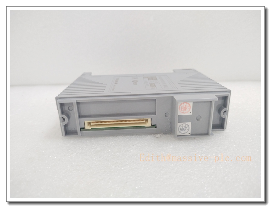
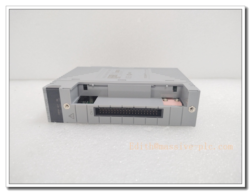
Description
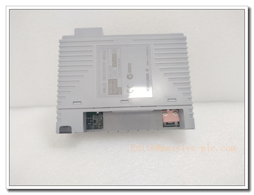
Yokogawa AAI835-H50 Isolated 4-Channel Analog I/O Module
Product Overview
The Yokogawa AAI835-H50 is a high-reliability hybrid analog input/output module purpose-built for the CENTUM VP and CS 3000 distributed control system (DCS) platforms, integrating 4 isolated 4–20 mA input channels and 4 isolated 4–20 mA output channels on a single compact unit. Equipped with full channel-to-channel and field-to-system electrical isolation, native HART communication pass-through support, and dual-redundant operation compatibility, it eliminates ground loop interference and signal cross-talk risks in complex industrial field environments. This module is widely deployed across process industries including petrochemical refining, power generation and pharmaceutical manufacturing, delivering stable high-precision signal acquisition and valve regulation for critical control loops.
Technical Specifications
| Parameter Category | Detailed Specification |
|---|---|
| Manufacturer | Yokogawa Electric Corporation |
| Product Type | Isolated Hybrid Analog Input/Output Module |
| Channel Configuration | 4 isolated 4–20 mA DC input channels + 4 isolated 4–20 mA DC output channels |
| Input Resistance | 290–450 Ω (power ON), ≥500 kΩ (power OFF) |
| Allowable Maximum Input Current | Up to 25 mA DC |
| Dielectric Withstanding Voltage | 500 V AC for 1 minute (between input/output and system, and across adjacent channels) |
| Power Requirement | 5 V DC at 320 mA, 24 V DC at 300 mA |
| Communication Feature | Native HART protocol pass-through support for smart field device configuration and diagnostics |
| Wiring Interface | ATI13S-00 pressure clamp terminal block, no soldering required for fast on-site wiring |
| Operating Temperature Range | 0°C to +55°C, standard industrial non-explosion-proof rating |
| Physical Weight | Approximately 300g |
| System Compatibility | Fully compatible with CENTUM VP R5.0 and later, and CS 3000 DCS platforms |
| Installation Method | Direct plug-in to ANB10D series ESB bus node unit backplane, supports hot-swap online replacement |
| Safety Compliance | CE, RoHS, UL, cUL global industrial safety certifications |
8 Recommended Related Yokogawa Models
- AAI835-S50 – Non-HART basic version of the AAI835 series, cost-effective for standard 4–20 mA signal loops without smart device requirements
- AAV144-S00 – 16-channel isolated analog input module, dedicated for large-scale process signal acquisition without output channels
- AAV544-S00 – 16-channel isolated analog output module, dedicated for multi-valve regulation control scenarios
- AAR145-S00 – 16-channel RTD temperature input module, seamlessly paired with AAI835-H50 for full process parameter monitoring
- ADV151-P50 – 32-channel isolated digital output module, expanding discrete interlock control capacity for the same FIO station
- ANB10D-425/CU2N – Dual-redundant ESB bus node unit, the mandatory backplane carrier for AAI835-H50 module installation
- PW482-10 – Dedicated DCS redundant power supply module, providing stable filtered 5V and 24V power for -H50 and adjacent I/O modules
- Yokogawa FieldMate Software Suite – Official HART device configuration tool, enabling full remote parameter setup and diagnostics for smart transmitters connected via -H50
Compatibility Notes & Critical Installation Pitfalls
- Intrinsic Safety Wiring Rule: This module cannot directly connect to hazardous zone 0/1 field devices; certified isolation barriers are mandatory for intrinsically safe applications, and Zener barriers are strictly prohibited as they will damage the module’s internal isolation circuit
- HART Bus Node Requirement: HART communication functionality can only be activated when paired with a HART-compatible ANB10D series ESB bus node unit; standard non-HART bus nodes will block all HART signal pass-through
- Forbidden Parallel Wiring: Neute signal cables parallel to high-power motor power lines within the same cable tray; this will introduce severe electromagnetic interference leading to signal drift and unstable readings
- Hot-Swap Precondition: Hot-swap replacement is only permitted under dual-redundant system configuration; removing the module while the system is running without prior backup will cause temporary signal loss for all 8 connected channels
- Grounding Isolation Mandatory: The module backplane grounding terminal must be connected to the independent DCS dedicated grounding grid; sharing grounding with high-power frequency converters will break the channel isolation effect and trigger ground loop faults
- Terminal Block Matching: Only the original ATI13S-00 pressure clamp terminal block is compatible; using third-party generic terminal blocks will cause loose wiring and intermittent signal disconnections under high vibration conditions
Standard Operating Procedure
- Pre-operation preparation: Fully back up the DCS I/O configuration and channel scaling parameters via the engineering station, confirm the target system versionrts HART functionality
- Field safety isolation: Close the on-site process isolation valves for all 8 connected channels, switch the corresponding control loops to manual mode to avoid unexpected process disturbance during module replacement
- Faulty module removal: Unlock the front panel mounting latch, pull tlty smoothly out of the ANB10D backplane, avoid scratching the backplane gold pin connectors during operation
- New module verification: Verifnew part number and suffix code, confirm no physical damage exists on all interface terminals and the isolation rating matches the original unit
- Installation and wiring: Insert the new module into the empty backplane slot, lock the mounting latch, then reconnect all field signal wires strictly following the original wiring diagram
- Power-on validation: Restore module power, confirm the RUN LED indicator stays solid green, and the system I/O management interface displays all 8 channels online with no fault alarms
- Function verification: Calibrate all 4 input channels with standard 4mA and 20mA signal sources, validate all 4 output channels can accurately output full-range 4–20 mA signals, and test HART communication with connected smart transmitters
- Final documentation: Update the equipment maintenance log with the new module serial number and firmware version, create a new full I/O configuration backup and store it in two independent offline storage locations
Typical Application Scenarios
- Petrochemical refining process units, where large ground potential differences demand full channel-to-channel isolation to eliminate signal interference
- Smart valve and transmitter integrated control loops, leveraging native HART support for remote device configuration and predictive maintenance diagnostics
- Small-scale chemical production facilities requiring both process signal acquisition and valve regulation on a single compact I/O module
- Thermal power plant boiler auxiliary control systems, delivering stable 4–20 mA signal regulation for feedwater flow and steam pressure control loops
- GMP-compliant pharmaceutical manufacturing workshops, meeting strict regulatory requirements for high-precision analog signal traceability and isolation safety
- Industrial wastewater treatment plants, managing chemical dosing pump flow regulation and water quality parameter monitoring on the same I/O station
Recommended Supporting Components
- Yokogawa FieldMate HART configuration software, enabling full remote parameter setup and diagnostics for all smart field devices connvia
- Certified shielded twisted-pair 4–20 mA signal cables, eliminating electromagnetic interference and ensuring stable signal transmission across long field distances
- Original ATI13S-00 pressure clamp terminal block, providing reliable vibration-resistant wiring for all 8 input/output channels
- Certified intrinsic safety isolation barriers, enabling safe conn of to field devices located in explosive hazardous zones
- Industrial-grade ESD anti-static operation kit, protecting the module mainboard PCB from electrostatic damage during maintenance
- ANB10D series HART-compatible ESB bus node unit, unlocking full HART communication pass-through functionality for the module