Description
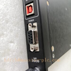
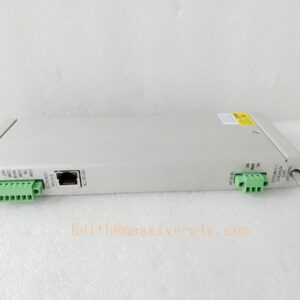
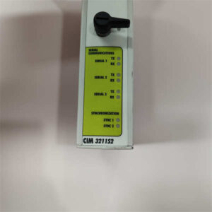
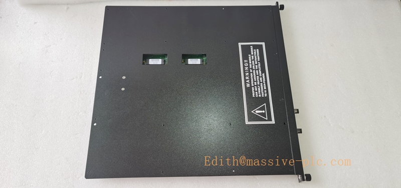
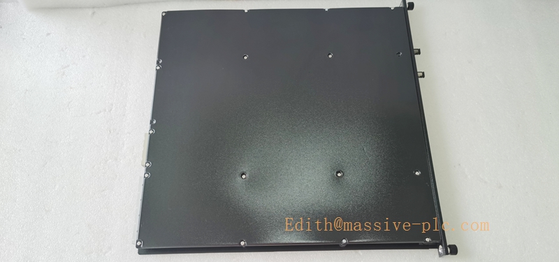
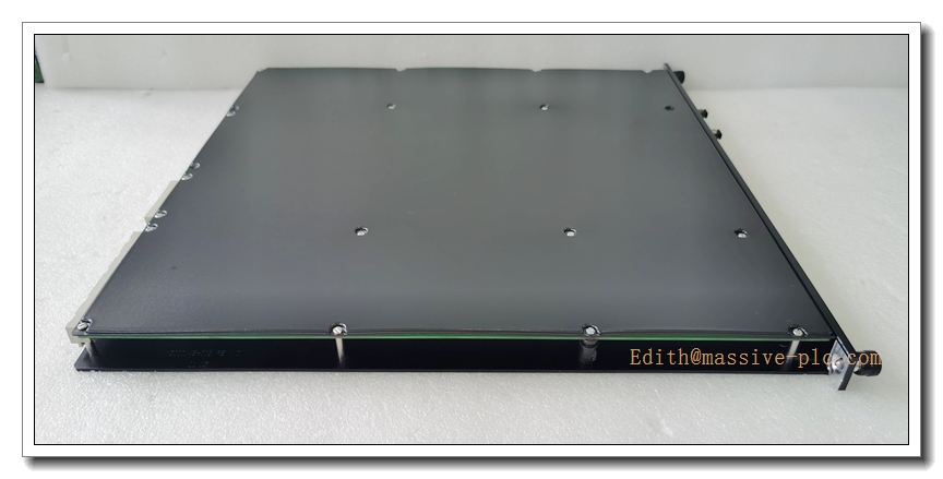
Triconex 4201 (RXM4201-3) Remote Extender Module Remote End
Product Title
Triconex 4201 (RXM4201-3) | TMR Multimode Fiber Remote Extender Triplet for Tricon Remote I/O Chassis
Product Description
The Triconex 4201, fully designated RXM4201-3, is the remote-side triple modular redundant fiber optic extender triplet matching the RXM4200-3 host module. It forms the optical communication link between the main Tricon SIS chassis and remote I/O expansion racks. This TMR triplet receives TriBus signals transmitted over multimode fiber from RXM4200-3, then converts optical data back to parallel backplane bus signals for local remote I/O modules. Built with 2oo3 voting architecture, it tolerates one independent channel failure without disrupting safety logic execution. Continuous onboard diagnostics monitor fiber link integrity, optical power loss, hardware faults and voter mismatches, feeding alarm information back to the main Tricon controller. Optical isolation eliminates ground loops and heavy electromagnetic interference between control room and field cabinets. It supports SIL3 safety applications under IEC 61508, and carries ATEX, FM and UL certifications for hazardous industrial environments.
Technical Specifications
| Item | Parameter |
|---|---|
| Brand | Triconex (Schneider Electric / Invensys) |
| Model | 4201 / RXM4201-3 |
| Module Type | Remote End Fiber Remote Extender Module (RXM), supplied as triplet (3 cards) |
| Architecture | TMR Triple Modular Redundant, 2oo3 fault tolerant voting |
| Fiber Medium | Multimode optical fiber |
| Maximum Link Distance | 2 km |
| Fiber Connector | ST type |
| Bus Interface | Tricon proprietary TriBus safety backplane bus |
| Communication Rate | 375 kbps |
| Isolation | Full galvanic optical isolation between main rack and remote I/O rack |
| Module Power | 24VDC supplied by remote RXM chassis backplane |
| Operating Temperature | -40°C ~ +70°C |
| Storage Temperature | -40°C ~ +85°C |
| Relative Humidity | 5%–95% non-condensing |
| Safety Certifications | SIL3 IEC61508, ATEX, FM, UL |
| Form Factor | Standard Tricon single-slot I/O module, three modules required per remote link |
| Enclosure Rating | IP20 when installed inside Tricon RXM expansion chassis |
| Diagnostics | Fiber break, optical attenuation loss, module hardware failure, voting discrepancy |
Compatibility & Installation Pitfalls
Compatibility
- Pairing Module: RXM4200-3 (host end triplet in main Tricon chassis)
- Host System: Tricon TMR SIS main chassis + RXM remote expansion chassis
- Configuration Software: TriStation 1131
- Fiber Cable: ST-terminated multimode fiber only; single-mode fiber incompatible
- Firmware: Tricon main CPU firmware must support RXM fiber expansion
- Not compatible: Trident, Tricon CX, generic third-party racks, single-mode RXM sets
Critical Installation Traps
- Must use complete triplet: 4201 only functions as a full set of three modules. Installing 1 or 2 cards cannot establish TriBus communication.
- Paired with RXM4200-3 only: Cannot mix single-mode RXM4211-3 with multimode 4201; optical transceivers differ and no link will form.
- Fiber connector contamination risk: Dirty, scratched or damaged ST end faces trigger intermittent link dropout. Always clean fiber tips before plugging in. Avoid sharp bends below fiber minimum bend radius.
- No hot-swap capability: RXM triplet modules do NOT support hot swap. Execute full LOTO and power down the remote chassis before removing or inserting any of the 4201 cards.
- Fixed dedicated slots: The three 4201 modules must occupy dedicated RXM processor slots in remote expansion rack. Ordinary I/O slots cannot run RXM extender functions.
- Grounding misunderstanding: Optical path removes ground loop risk, but remote cabinet protective earth must be properly bonded. Poor cabinet grounding can corrupt power supply and induce EMI.
- Distance limitation: Maximum 2 km multimode fiber length. Exceeding this limit causes excessive optical attenuation and frequent link fault alarms.
Standard Operating Procedure (SOP)
- Pre-Installation Check & LOTO Perform lock-out tag-out procedure, fully de-energize both main Tricon chassis and remote RXM expansion chassis. Inspect the 4201 triplet for PCB damage, bent ST fiber ports or corrosion. Confirm revision matches system BOM. Prepare ESD wristband and fiber cleaning kit.
- Triplet Module Mounting Insert the three RXM4201-3 modules into the designated RXM processor slots of the remote expansion chassis. Fully seat each card and tighten front panel fixing screws.
- Fiber Cabling Interconnection Clean ST fiber end faces. Route three multimode fiber cables from RXM4200-3 (main rack) to RXM4201-3 (remote rack). Apply strain relief on fiber cables; avoid tight sharp bends.
- TriStation Hardware Configuration Open TriStation 1131. Add remote RXM chassis and fiber link into the hardware tree, configure rack address and communication fault timeout parameters. Download compiled project to Tricon main processor.
- Power-Up and Commissioning Power up main chassis first, then remote RXM chassis. Wait for automatic self-test cycle. Check front panel LED indicators, verify all three optical links show PASS status. Simulate fiber break test to validate diagnostic alarm response.
- Continuous Operation & Diagnostics Monitor fiber attenuation, link status and fault logs via TriStation or plant HMI. Conduct periodic optical attenuation testing for SIL proof test audit records.
- Module Replacement Workflow Activate LOTO for remote RXM chassis power. Disconnect ST fiber connectors. Remove the faulty module from triplet slot. Install spare 4201 module, reconnect cleaned fiber cables. Restore rack power, verify link synchronization and diagnostic status.
Application Scenarios
- Oil & Gas ESD emergency shutdown systems with distributed field I/O cabinets
- Petrochemical & refinery SIL3 safety instrumented control loops
- Fire and gas (F&G) systems with remote field racks
- Power plant boiler and turbine safety protection
- LNG terminal distributed safety interlock
- Pipeline emergency isolation valve control
- Offshore platform remote safety I/O enclosures
Supporting Components
- Tricon RXM Remote Expansion Chassis
- RXM4200-3 Host-side fiber extender triplet
- ST-terminated multimode optical fiber cables
- Tricon TMR Main Chassis
- TriStation 1131 Configuration Software
- Tricon Chassis 24VDC Power Supply
- Tricon Main Processor Module
- Fiber cleaning kit & optical power meter
- Anti-static wristband and ESD mat
- Filler blank panels for unused chassis slots
Related Model Recommendations (10 Models)
- RXM4200-3: Host multimode fiber triplet, paired with 4201
- RXM4210-3: Host single-mode RXM triplet (long distance up to 12km)
- RXM4211-3: Remote end single-mode RXM triplet for 12km links
- 3009: Tricon main processor module
- 3624: 16-channel TMR supervised digital output module
- 3504E: 64-ch non-isolated TMR digital input
- 3704E: 64-ch high density TMR analog input
- 3721: TMR analog output module
- 4119A: Enhanced intelligent communication module
- 3601E: TMR supervised digital output module