
Description
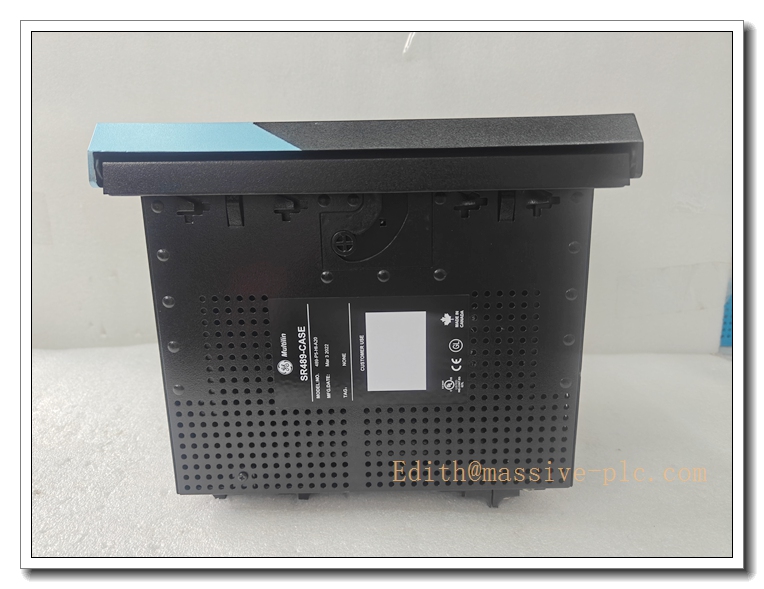
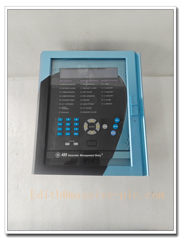
SR489-P5-LO-A20-E GE Multilin Generator Management Relay, 5A CT, 4-20mA AO, Low Control Power
Product Application
SR489 is a dedicated multifunction generator protection relay for medium/small synchronous and induction generators. It delivers primary and backup electrical fault protection plus thermal monitoring for stator and bearings. This model provides 4 isolated 4–20mA analog outputs for sending real-time generator parameters to DCS/PLC (e.g. IC695ETM001, VersaMax). It records events and oscillography for post-fault analysis, supports breaker control, synchronism check and generator motoring protection. Typical sites: CHP combined cycle, diesel/gas gen-set, captive power plant, backup generator protection.
SR489-P5-LO-A20-E
Product Specifications
- Part Number: SR489-P5-LO-A20-E
- Manufacturer: GE Multilin / GE Vernova
- Product Type: Generator Management Multifunction Protection Relay
- CT Input: 5A secondary (P5)
- VT Input: 4 voltage transformer inputs
- Control Power (LO): 20–60 VDC or 20–48 VAC (48–62Hz)
- Analog Output (A20): 4 × isolated 4–20mA
- RTD Input: 12 channels for stator / bearing temperature monitoring
- Digital Inputs: 9 programmable dry-contact digital inputs
- Relay Outputs: 6 × Form-C trip/alarm relay contacts
- Communication: Front RS232, rear dual RS485
- Protocols: Modbus RTU, DNP3.0 (option)
- Sampling Rate: 12 samples per cycle
- Event Recorder: 40 events with time stamp
- Oscillography: 64 cycles fault waveform capture
- Frequency Support: 25 / 50 / 60Hz
- Display: Front panel 40-character LCD + keypad & LED status indicators
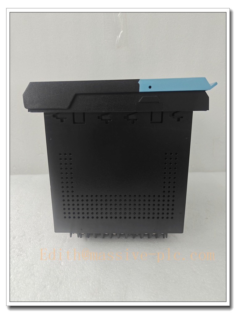
- Construction: Drawout case with automatic CT shorting on withdrawal
- Mounting: Panel mount
- Operating Temperature: -40 ℃ ~ +60 ℃
- Humidity: 5% ~95% RH non-condensing
- Pollution Degree: 2
- Product Status: Mature legacy protection relay, spares & service available
- Approx. Weight: 7.7 kg
Core Technical Parameters
- Protection elements: % stator differential, 100% stator ground fault, negative sequence overcurrent, loss of excitation, reverse power (anti-motoring), over/under voltage, over/under frequency, phase overcurrent, thermal overload
- RTD thermal model: uses stator/bearing RTDs to bias overload curve, sensor open/short detection
- Drawout design: CT shorting mechanism prevents dangerous open CT condition when relay pulled out
- 4-20mA AO channels assignable to real values: MW, Mvar, voltage, current, temperature etc.
- IRIG-B time synchronization option for high-precision event timestamp
- 489PC software for setpoint configuration, metering view, oscillography download and relay simulation
- Flash memory for firmware upgrade without hardware replacement
Recommended Matching Spare Parts & Accessories (8 Items)
- 5A CTs & generator neutral core-balance CT
- Voltage transformers VT
- RTD sensors (stator & bearing PT100)
- Shielded twisted pair signal cables
- 489PC configuration software
- Replacement drawout case contacts
- IRIG-B time sync module (if required)
- Surge protection modules for CT/VT/RTD wiring
SR489-P5-LO-A20-E
Product Features
✅ Full Suite Generator Protection Differential, stator ground, loss of excitation, reverse power, thermal overload and frequency/voltage protection for generator main and backup protection.
✅ 12-Channel RTD Temperature Monitoring Monitor stator winding and bearing temperatures, thermal model protects against overheating, RTD fault detection.
✅ 4 Isolated 4–20mA Analog Outputs Transmit generator operating parameters to DCS/PLC analog inputs.
✅ Drawout Construction with Auto CT Short When relay withdrawn, CT secondary automatically shorted for safety, simplify maintenance.
✅ Multiple Serial Communication Ports Front RS232 local commissioning; dual rear RS485 for SCADA/Modbus RTU to PLC/DCS.
✅ Event Log & Oscillography 40 event records and 64-cycle oscillography for fault post-mortem analysis.
✅ Wide Range Low Control Power Supply 20–60VDC / 20–48VAC, tolerant of auxiliary power fluctuation in power plants.
Installation Guidelines
- Install relay into control panel cutout, secure drawout housing.
- Wire CT, VT, RTD, digital inputs and trip relay outputs per single-line diagram.
- Connect control power (20–60VDC / 20–48VAC).
- Wire RS485 Modbus bus to DCS/PLC or RS232 to local laptop.
- Use 489PC or front keypad to configure CT/VT ratios, generator rated parameters, protection setpoints and 4–20mA assignments.
- Perform secondary injection test to verify all protection elements and I/O.
- Test breaker trip/alarm outputs, event recording and oscillography function.
- Complete generator static test and synchronizing test before generator rolling.
Maintenance Instructions
Daily Maintenance Check front panel LED/LCD for relay health, alarms and metering values; monitor generator protection alarms in SCADA.
Periodic Maintenance (Every 6–12 months) Inspect CT/VT wiring, RTD cable integrity; check drawout contacts; backup relay setting file. Perform secondary injection test per protection maintenance schedule.
Fault Maintenance
- Relay fault / self-test alarm: inspect control power supply, check drawout contacts.
- Protection misoperation: review oscillography and event log, verify CT/VT wiring and setpoints.
- 4-20mA AO abnormal: check analog output assignment, loop wiring and load resistance.
Do not modify generator protection setpoints without power system protection engineer approval.
Long-Term Operation Tips Maintain panel temperature -40~+60℃. Store spare SR489-P5-LO-A20-E in dry anti-static environment, always backup setting file.
Brand Same‑Series Models (6 Models)
- SR489-P5-LO-A20-E – Target model,5A CT, low power,4-20mA AO
- SR489-P1-HI-A20-E – 1A CT, high control power variant
- V7768-320000 – VME single board computer
- IC695ETM001 – RX3i Ethernet module
- GF868-1-2-1-2-1-B-1-4-0-0-0 – Panametrics ultrasonic flowmeter
- IS200TRLYS1B – Mark VI relay output board

 Start Chat




