
Description
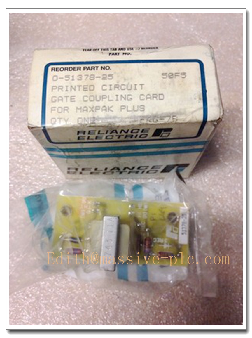
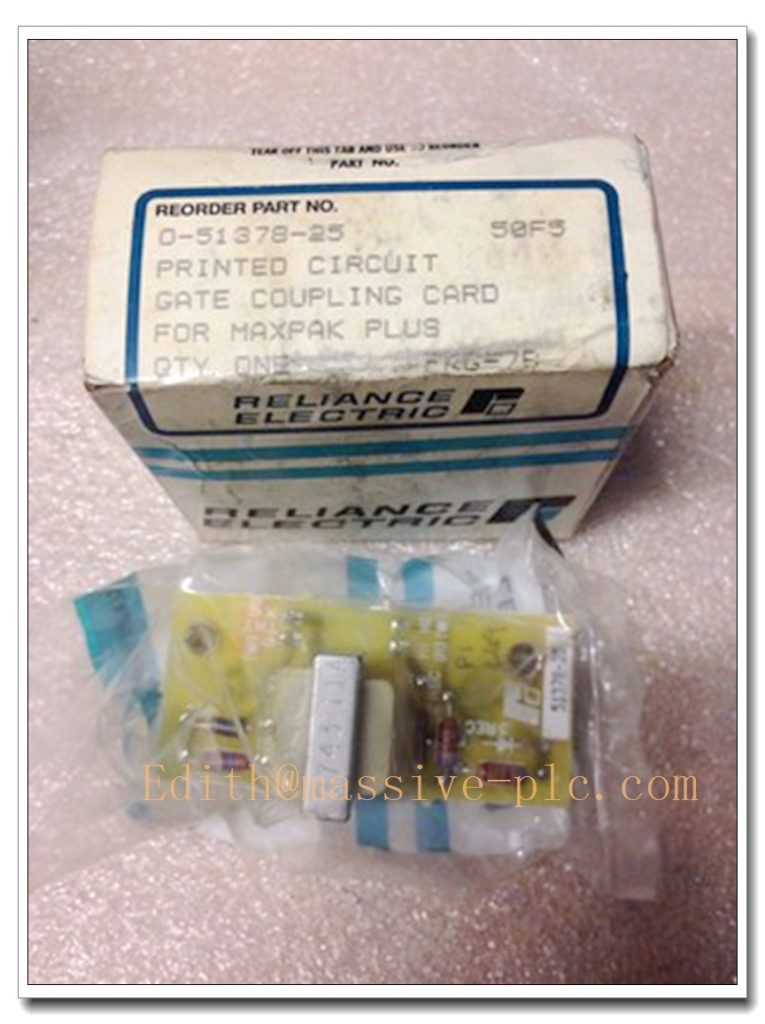
Reliance Electric 0-51378-25 Gate Coupling Board for MaxPak Plus Rectifier Stack Drives
Core Product Overview
The 0-51378-25 is a legacy gate coupling PCB designed and manufactured by Reliance Electric (later Baldor-Reliance). It serves as the pulse trigger interface for SCR rectifier stacks within the MaxPak Plus DC drive platform. This small auxiliary board transfers firing control signals to thyristor assemblies, synchronizing gate pulses for controlled rectification and DC power regulation. It is a discontinued original OEM component widely used in heavy-duty DC motor drives.
Main Technical Specifications
- Part Number: 0-51378-25
- Product Type: Gate Coupling Board (SCR Trigger Interface)
- Platform: MaxPak Plus Rectifier Stack
- Connector: 2-pin interface
- Function: Gate pulse coupling & isolation for SCR rectifiers
- Mounting: Direct mounting on Reliance rectifier stack assemblies
- Status: Obsolete / Discontinued by OEM
- Construction: Through-hole printed circuit board with pulse transformer, resistors and capacitors
- Working Environment: Industrial cabinet, ambient -10°C ~ +55°C
- Humidity: 5% to 95% non-condensing
- Compatibility: Matches Reliance rectifier assemblies including 86466-58R and related MaxPak power stacks
0-51378-25
Same-Series Model Recommendations (8 Models)
- 0-51378-15: Gate coupling board, early MaxPak version, 2-pin
- 0-51378-20: Gate coupling board, mid-revision MaxPak
- 0-51378-25: Standard MaxPak Plus gate coupling board (subject model)
- 0-51378-30: Upgraded pulse-coupling variant with noise filtering
- 0-51379-10: Auxiliary gate trigger board for high-current MaxPak stacks
- 0-48688-00: SCR snubber board for MaxPak rectifier modules
- 0-51178-01: Gate pulse amplifier board for DC drives
- 0-51258-01: Isolated gate interface for older Reliance DC drives
Professional Quality Control & Testing SOP
All refurbished or surplus 0-51378-25 boards follow this inspection and validation workflow:
- Visual Inspection: Check PCB traces, solder joints, pulse transformer, capacitor and resistor integrity; verify no burn marks, corrosion or cracked components.
- Continuity & Resistance Test: Measure passive component values, coil winding resistance of pulse transformer, check for shorted tracks.
- Isolation Resistance Test: Verify insulation between primary and secondary of the gate pulse transformer.
- Pulse Signal Simulation: Inject low-level trigger pulses to validate pulse coupling and waveform integrity.
- Thermal Screening: Run board at rated cabinet temperature to detect intermittent cold/solder joint faults.
- Vibration Screening: Light mechanical vibration test to expose loose solder joints (for refurbished units).
- Functional Bench Test: Pair with compatible rectifier stack simulator to confirm gate pulse delivery timing.
- Final Cleaning & Packaging: Ultrasonic flux cleaning, conformal coating touch-up if required, anti-static packaging.
New / Refurbished Board Installation Instructions
- Pre-Installation Safety: Lock out and tag all AC and DC power; fully discharge DC bus capacitors on the rectifier stack.
- Cabinet & Rectifier Inspection: Clean the rectifier stack and mounting area of dust, carbon dust and coolant residue.
- Mechanical Mounting: Fix the gate coupling board onto the designated bracket on top of the SCR stack, do not over-tighten PCB mounting screws.
- Wiring & Connector Fit: Align the 2-pin connector firmly; confirm no bent pins. Follow factory wiring diagram for pulse routing to SCR gates.
- Pre-Power Megger Check: Confirm no unintended short circuits between gate, cathode and power bus.
- Commissioning: Power up drive without load first, check for stable firing sequence, no misfire or excessive noise; then perform gradual load test.
- Post-Service: Record waveform data for maintenance reference.
Application Scenarios & Product Features
Typical Applications
- Reliance MaxPak Plus DC variable speed drives
- Heavy industry DC motor control: metal rolling, extruders, paper machines, winders
- Electroplating and DC power rectifier systems
- Mining, crane and hoist DC drive retrofits
- Legacy plant upgrade, spare part replacement for old Reliance drive systems
Key Features
- Compact pulse-transformer isolated gate coupling for SCR rectifiers
- Designed to match the timing requirements of MaxPak Plus firing circuits
- Simple through-hole robust design for decades of industrial service
- Direct stack mounting form factor, original OEM spare
- Transfers low-level logic firing pulses to high-potential thyristor gates, providing electrical isolation
Frequently Asked Questions (FAQ)
Q1: What does the 0-51378-25 do? A1: It is a gate coupling board. It receives low-level firing pulses from the drive control logic, uses a pulse transformer to isolate and deliver trigger pulses to the SCR gates on the MaxPak Plus rectifier stack.
Q2: Is this part still manufactured by Reliance / Baldor? A2: No. The 0-51378-25 is fully discontinued. Available stock is surplus, used or professionally refurbished. No new OEM production.
Q3: Can I substitute it with another Reliance gate board directly? A3: Not without verification. Pinout, pulse transformer ratio and physical mounting must match. 0-51378-xx revisions are not always plug-and-play.
Q4: What are common failure modes of this board? A4: Open pulse transformer windings, dried or shorted snubber capacitors, cracked solder joints from thermal cycling, carbon contamination causing tracking and leakage.
Q5: Can it be hot-swapped while the MaxPak drive is energized? A5: Absolutely not. The rectifier stack carries high DC bus voltage. All power must be locked out and capacitors fully discharged before removal or installation.


 Start Chat




