Description
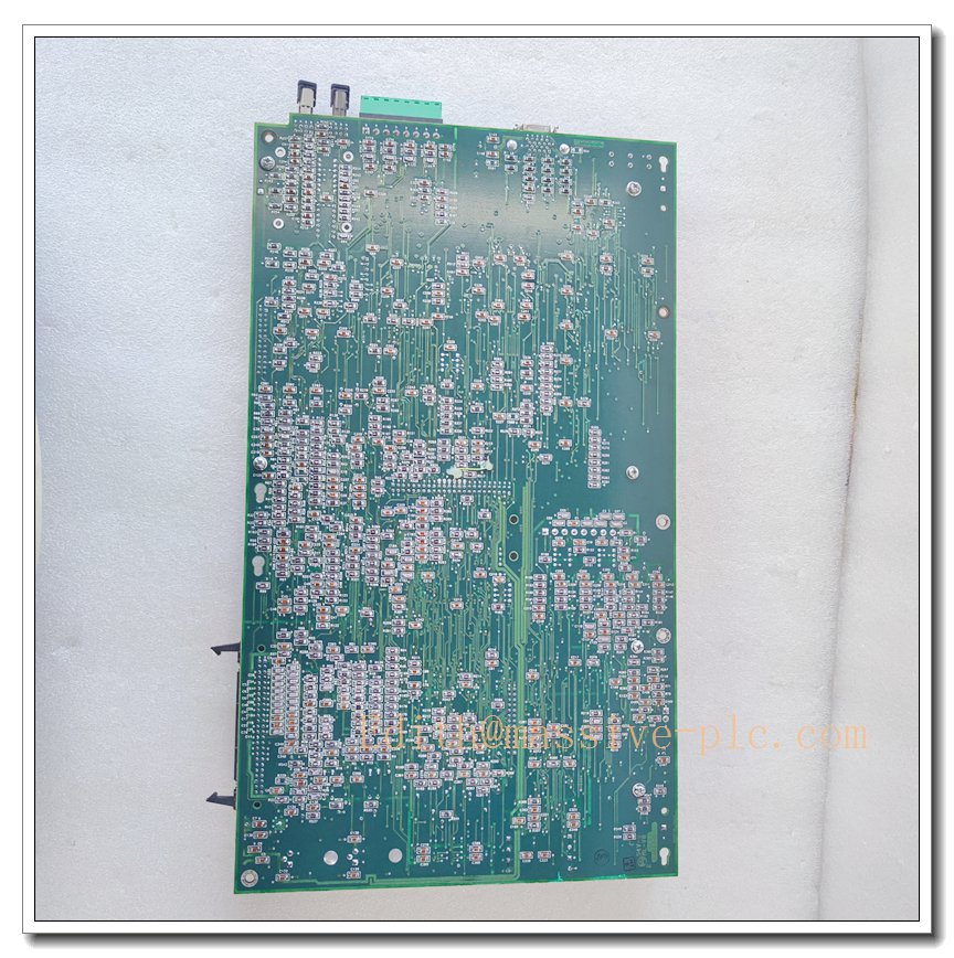
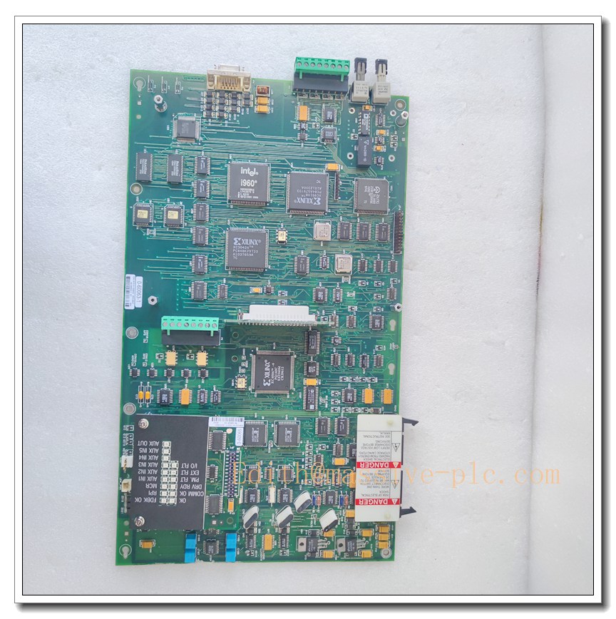
RELIANCE 0-60063-1 Auxiliary Power Supply Board, SA3000 PMI Rack Logic Power Module
Product Introduction
The RELIANCE 0-60063-1 is a rack-mounted auxiliary logic power supply board developed for Reliance AutoMax SA3000 PMI high-power drive racks. It converts the raw incoming auxiliary AC supply into multiple regulated DC voltage rails to power PMI processor, analog feedback, fiber interface and other control cards within the drive chassis. This legacy power board incorporates rectifier circuits, filter networks and multi-channel overvoltage / overcurrent protection circuits. Front panel LED provides simple power health indication. As a critical spare component for SA3000 drive maintenance and retrofit projects, it is widely used in metal rolling mills, pulp and paper production lines, heavy material-handling drives. OEM original production has been discontinued. Built with robust EMC filtering and vibration resistance, it meets UL and CE industrial standards for continuous operation in dusty, electrically noisy factory environments.
Technical Introduction
- Product Type: Auxiliary Logic Power Supply Module
- Brand: RELIANCE Electric
- Model: 0-60063-1
- Applicable Platform: AutoMax SA3000 PMI Drive Rack
- Input: Auxiliary AC supply from drive cabinet
- Output: Multiple regulated DC rails for PMI rack control electronics
- Front Panel: Power OK status LED indicator
- System Interface: Rear edge connector for rack power distribution
- Mounting: Plug-in rack card with dual faceplate locking screws
- Operating Temperature: 0°C ~ +60°C
- Humidity: 5% to 90% non-condensing
- Protection: Overvoltage shutdown, overcurrent limiting, short-circuit protection, thermal cutback
- Core Functions: AC rectification, multi-rail DC voltage regulation, power distribution to all PMI rack plug-in modules, power rail fault monitoring, loss-of-power alarm reporting
- Typical Applications: SA3000 high-power AC & DC variable speed drives, rolling mill main drives, paper machine sectional drives, heavy-duty industrial conveyor drive systems
0-60063-1
Adaptive Quality Assurance & Test Protocol
Each 0-60063-1 auxiliary power supply module undergoes full adaptive validation workflow prior to shipment to guarantee output stability and long-term field reliability.
- Visual & Physical Inspection: Complete screening of PCB, transformer, electrolytic capacitors, solder joints, connectors and faceplate; inspect for oxidation, bulging capacitors, burnt traces or bent pins.
- Power Cycling Burn-in Test: Continuous powered burn-in plus repeated AC power on/off cycles to eliminate early failure of semiconductors and passive components.
- Multi-Rail Output Regulation Test: Apply nominal and fluctuating AC input; measure all DC output rails under light, nominal and full load conditions to verify voltage accuracy and ripple performance.
- Rack Integration Test: Install into matching PMI rack to verify power sequencing, distribution to backplane and Power OK LED indication.
- Protection Trigger Test: Simulate overvoltage, overcurrent and short-circuit events to confirm protective shutdown and fault response.
- EMI Immunity Adaptive Test: Apply simulated conducted industrial interference to confirm stable DC outputs under noisy plant power supply conditions.
- Temperature Cycling Screening: Thermal cycle test to confirm output consistency across the full rated operating temperature range.
- Final Functional Report: Generate unique traceable test log for each unit. Acceptance criteria include tight voltage regulation, low ripple, reliable protection response and valid power OK signal. All test records are retained for traceability.
Field Engineer Technical Notes
This auxiliary power board supplies low-voltage logic power to all PMI rack control modules. Installation, commissioning and troubleshooting must be performed by qualified technicians with high-voltage safety training and SA3000 PMI drive experience.
- Installation: Fully isolate and lock out all AC mains and DC bus power of the PMI rack before inserting the card. Align rear edge connector correctly and tighten faceplate locking screws. Verify protective earth grounding of the entire drive cabinet.
- Wiring: Use rated wiring for auxiliary AC input. Separate power input wiring from sensitive analog and fiber signal cables to reduce noise coupling. Torque terminals to specified values to avoid loose connections.
- Commissioning: After power restoration, confirm Power OK LED illuminates normally. Measure each DC output rail at nominal load and validate voltage tolerance. Check power sequencing behaviour during rack power-up and power-down.
- Troubleshooting: Common faults include missing DC rails, high output ripple, intermittent power drop and Power OK LED off. Distinguish between incoming auxiliary supply failure and internal component degradation on the module.
- Maintenance: Periodically inspect capacitors and connector terminals for dust, corrosion or swelling. Always fully de-energize the entire drive system before removing the module. Operating the drive with unstable auxiliary power can cause random control card resets, communication dropout and unplanned drive trips.
- Compatibility Notice: Confirm PMI rack hardware revision before replacement. Mismatched module revision may lead to incorrect power sequencing and false power-fault alarms.
8 Related Models in the Same Series
- 0-60063-2
- 0-60063-3
- 0-60063-4
- 0-60063-5
- 0-60063-6
- 0-60063-7
- 0-60063-8
- 0-60063-9