Description
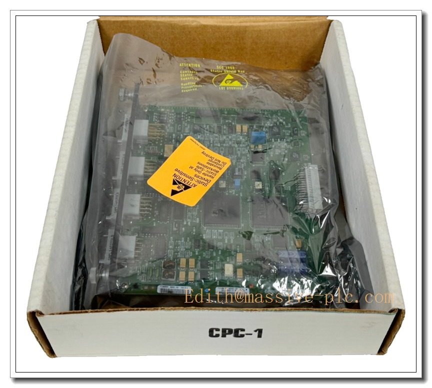
RELIANCE 0-60002-6 DC Power Technology Module, AutoMax PMI DC Drive Control Card
Product Introduction
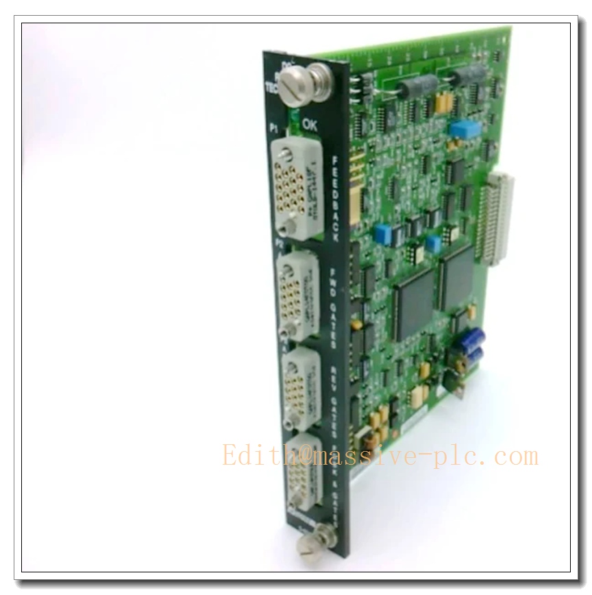
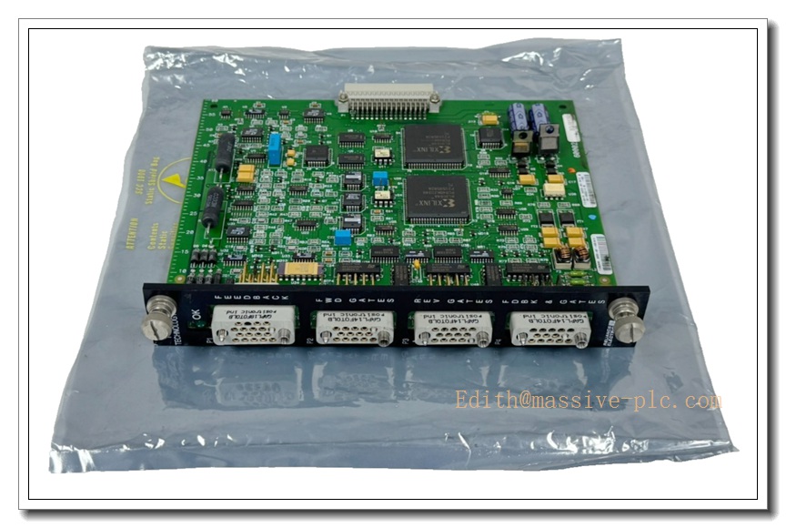
The RELIANCE 0-60002-6 is a rack-pluggable DC power technology module built for Reliance AutoMax PMI DC drive control platforms. It digitizes armature and field power feedback signals and feeds processed data to the main drive controller for armature current regulation, field excitation control and closed-loop DC motor speed regulation. This legacy control board integrates dual Xilinx FPGAs, multi-channel signal conditioning circuits and front-panel heavy-duty connectors, engineered for heavy industrial DC drive applications such as metal rolling mills, paper machines and large material handling equipment. Equipped with dedicated gate drive and feedback ports, the module samples high-power drive-side analog signals, isolates and converts them into digital values for drive control algorithms. It is widely supplied as spare replacement part for retrofit and maintenance of existing Reliance DC drive systems. This product is OEM discontinued and complies with UL and CE industrial standards, featuring robust EMC protection to withstand vibration and electrical noise in heavy manufacturing environments.
Technical Introduction
- Product Type: DC Power Technology / Drive Signal Digitizing Module
- Brand: RELIANCE Electric
- Model: 0-60002-6
- Platform: AutoMax PMI DC Drive Rack System
- Core Hardware: Dual Xilinx XC3064A FPGAs, multi-channel analog signal conditioning
- Front Panel Interface: 4 female multi-pin connectors for Feedback, Forward Gates, Reverse Gates and composite gate/feedback signals
- Backplane Connector: Edge male connector for PMI rack bus communication
- Status Indicator: Green “OK” LED for module health status
- Mounting: Rack insertion design, 2 faceplate locking screws
- Operating Temperature: 0°C ~ +60°C
- Humidity: 5% to 90% non-condensing
- Main Functions: Armature & field current signal sampling, analog-to-digital conversion, gate signal interface, fault detection of drive power circuits, data transmission to master drive controller for closed-loop regulation
- Typical Applications: DC drive control for rolling mills, paper processing lines, heavy-duty conveyor drives, large industrial DC motor speed control
0-60002-6
Adaptive Quality Assurance & Test Protocol
Each 0-60002-6 module undergoes full adaptive validation workflow prior to shipment to guarantee hardware integrity and long-term field reliability.
- Visual & Physical Inspection: Complete visual screening of PCB, FPGAs, capacitors, solder joints, connectors and faceplate; inspect for oxidation, bent pins, burn marks or mechanical damage.
- Power Cycling Burn-in Test: Continuous powered burn-in plus repeated power on/off cycles to expose early failure of semiconductors and passive components.
- Signal Simulation Test: Precision signal source injects simulated armature and field feedback signals to verify sampling accuracy, linearity and FPGA logic response.
- Rack Bus Communication Test: Insert into matching PMI rack to validate backplane handshake, real-time data transmission and OK LED status.
- Gate Interface Functional Test: Verify forward/reverse gate signal transmission and signal integrity under load simulation.
- EMI Immunity Adaptive Test: Apply simulated industrial conducted and radiated interference to confirm stable signal sampling under noisy field conditions.
- Temperature Cycling Screening: Thermal cycle test to confirm consistent performance across rated operating temperature range.
- Final Functional Report: Generate unique traceable test log for each unit. Pass criteria include accurate power signal conversion, stable bus communication, correct fault flag triggering and valid OK LED indication. All test records are retained for traceability.
Field Engineer Technical Notes
This DC drive control module handles high-power motor feedback signals; installation, commissioning and troubleshooting must be performed by qualified field technicians with DC drive experience.
- Installation: Fully power down the PMI drive rack and isolate high-voltage DC bus before card insertion. Align rear edge connector correctly and tighten top/bottom locking screws. Ensure rack protective earth grounding is fully implemented.
- Wiring: Use heavy-duty shielded cables for feedback and gate wiring. Separate low-level signal wiring from high-current power cables. Apply single-point shield termination to avoid ground loops.
- Commissioning: After power-up, verify the OK LED illuminates normally. Run armature and field current offset calibration. Compare sampled values against physical meter readings at motor terminals. Test forward/reverse gate firing sequence.
- Troubleshooting: Common faults include missing gate signals, abnormal armature/field current readings, LED not lit and communication loss. Use drive diagnostic registers to distinguish high-side power circuit faults versus module hardware defects.
- Maintenance: Periodically inspect connector pins for dust, corrosion and loose terminals. Always fully de-energize the entire drive system before removing the module. Do not operate DC motor with degraded feedback sampling, as this may cause motor overspeed or power device burnout.
- Compatibility Notice: Confirm PMI rack hardware revision and drive firmware before retrofit. Mismatched firmware or rack version may lead to unstable current regulation and intermittent drive trips.
8 Related Models in the Same Series
- 0-60002-1
- 0-60002-2
- 0-60002-3
- 0-60002-4
- 0-60002-5
- 0-60002-7
- 0-60002-8
- 0-60002-9