
Description
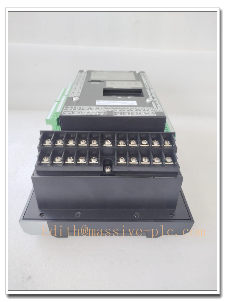
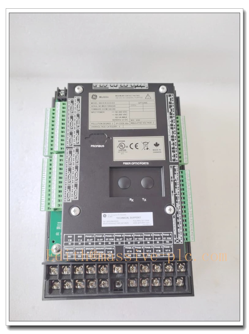
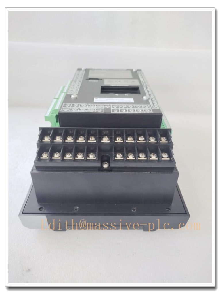
GE Multilin 369-HI-R-0-0-0 Motor Management Relay for Medium & Large Three-Phase AC Motors
Core Product Overview
The 369-HI-R-0-0-0 is a multifunctional motor management relay from GE Multilin (now part of GE Vernova) 369 series. It delivers integrated motor protection, real-time metering, sequence control and condition monitoring for critical three-phase AC motors. This unit supports adaptive motor characteristic learning, automatically capturing motor inrush, thermal cooling and acceleration profiles to optimize protection curves. It is equipped with local LCD readout, configurable output relays, waveform capture, event logging and serial communication interfaces. Widely deployed in power plants, water treatment, mining, oil & gas and heavy process industries, it is a mature legacy protection device commonly supplied as surplus, tested and refurbished spare parts for motor control centers.
Main Technical Specifications
- Part Number: 369-HI-R-0-0-0
- Manufacturer: GE Multilin / GE Vernova
- Product Family: 369 Motor Management Relay
- Device Type: Motor Protection & Management Relay
- Control Power: 40–265 VAC / 50–300 VDC
- Nominal Burden: 20 VA, Max 65 VA
- CT Secondary Rating: 1 A or 5 A configurable
- Frequency Range: 20 Hz ~ 100 Hz
- RTD Input: 12 channels, 3-wire; supports Pt100, Ni100, Ni120, Cu10
- Communication: Non-isolated RS232 local port, RS485 for Modbus RTU
- Display: 40-character LCD, status LED indicators
- Data Recording: Event reports, startup logs, waveform capture (3 buffers, 16 cycles each)
- Protection Functions: Overload, phase loss, phase unbalance, ground fault, undervoltage, overvoltage, stall, jam, reverse power, starter failure
- Operating Temperature: -40°C ~ +70°C
- Humidity: 5%–95% non-condensing
- Enclosure: Panel mount, IP30
- Dimensions: 296 mm H × 107 mm W × 205 mm D
- Certifications: UL, CE
- Status: Legacy platform, original OEM production discontinued; available as surplus or professionally bench-tested refurbished units
Same-Series Model Recommendations (8 Models)
- 369-HI-R-0-0-0: Base motor management relay (subject model, no extra metering package)
- 369-HI-R-M-0-0-0: Variant with full metering package, power & energy measurement
- 369-HI-R-M-0-0-0-E: Metering version plus enhanced diagnostics and audit trail
- 369-HI-R-0-0-0-E: Base relay with enhanced event recorder and security functions
- 369-HI-R-F-0-0-0: Model with optional fiber-optic communication port
- 369-HI-L-0-0-0: Low auxiliary power variant for restricted control voltage supplies
- 369-HI-R-M-F-0-0-0: Top configuration with metering + fiber communication
- 369-LO-R-0-0-0: Compact basic version for smaller MCC motor applications
Professional Quality Control & Testing Standard Operating Procedures
All surplus and refurbished 369-HI-R-0-0-0 relays follow this inspection workflow:
- Visual & Mechanical Inspection: Examine front panel, LCD, keypad, terminal blocks and PCB for burn marks, corrosion, cracked solder or physical damage; verify part label legibility.
- Auxiliary Power Bench Test: Apply rated AC/DC control power, confirm stable internal rails and no power supply fault.
- Display, Keypad & LED Test: Validate LCD pixel integrity, keypad response, alarm/trip indicator lamps.
- Protection Element Simulation: Inject calibrated current/voltage signals to test overload, unbalance, ground fault, stall and undervoltage pickup & timing.
- RTD Channel Test: Feed precision resistance values into each RTD input and verify accurate temperature reading.
- Communication Interface Test: Test RS232 local access and RS485 Modbus RTU polling with relay configuration software.
- Data Logging & Waveform Capture Test: Trigger fault records, confirm event timestamps and waveform buffer storage.
- Final Cleaning & Packaging: Clean terminals and PCB, reset relay settings to factory default, apply ESD packaging with test certificate.
New / Refurbished Relay Installation Guidelines
- Pre-Installation Safety: Implement lockout-tagout procedures; isolate MCC control power, CT and VT secondary circuits to prevent hazardous voltage.
- Panel Location Check: Select motor control cabinet location free of excessive heat, vibration and corrosive gas; maintain clearance for ventilation and wiring access.
- Mechanical Mounting: Install relay into standard panel cutout; secure mounting latches evenly without over-tightening to avoid front panel distortion.
- Secondary Wiring: Connect CT, VT, RTD sensors, control power and output contact wiring; route instrument wiring separately from high-current cables to reduce EMI. Torque terminals per GE drawing specifications.
- Relay Configuration: Use GE 369 Setup software or front keypad to enter motor nameplate data, CT ratios, protection curve settings, alarm thresholds and Modbus address.
- Pre-Commissioning Functional Test: Power up relay without primary motor energization; simulate faults to verify trip contact operation, LED alarms and SCADA Modbus data.
- Commissioning & Baseline Recording: Energize motor under supervised conditions; record startup waveforms, thermal load trends and confirm all protection elements operate as intended; save setting file for archive.
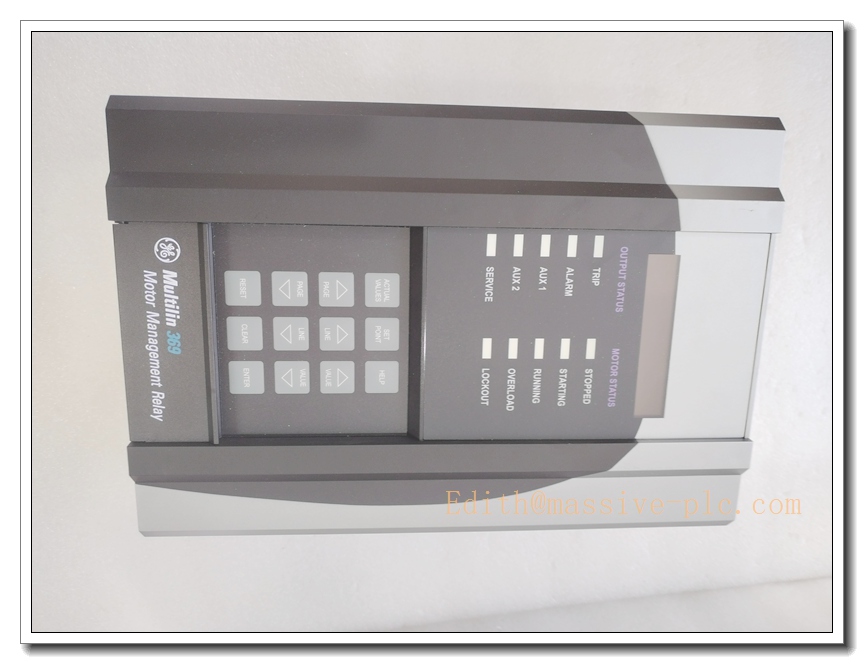
369-HI-R-0-0-0
Application Scenarios & Product Features
Typical Application Scenarios
- Medium and large three-phase AC motors in Motor Control Centers (MCC)
- Power plant auxiliary pumps, fans, crushers and conveyors
- Mining hoists, material handling and mineral processing equipment
- Oil & gas compressors, feed pumps and hazardous area motor systems
- Water and wastewater treatment large pumping stations
- Retrofit spare replacement for existing GE 369 relay installations in industrial plants
Core Product Features
- Adaptive thermal overload protection that learns motor thermal characteristics
- Rich protection suite covering electrical and mechanical motor failure modes
- 12 RTD temperature inputs for bearing and stator winding thermal monitoring
- Local LCD and status LEDs for on-site troubleshooting and trip indication
- Built-in waveform capture and sequence-of-event logging for post-fault analysis
- RS485 Modbus RTU for integration with DCS and SCADA systems
- Panel-mount design optimized for standard MCC compartments
- Proven long-term field reliability for continuous-duty critical motors
Frequently Asked Questions (FAQ)
Q1: What is the difference between 369-HI-R-0-0-0 and 369-HI-R-M-0-0-0? A1: The M suffix denotes the optional metering package. The 369-HI-R-0-0-0 is the base protection unit; the M version adds advanced power, demand and energy metering functions.
Q2: Is the 369-HI-R-0-0-0 still manufactured by GE Vernova? A2: No. The 369 series is an obsolete legacy relay. Available stock consists of surplus or professionally refurbished, fully bench-tested units.
Q3: Can this relay protect VFD-fed motors? A3: It can be applied for auxiliary protection, but CT measurement and protection curves must be carefully adjusted for variable-frequency waveforms. Direct VFD output protection has limitations.
Q4: What are common failure modes of the 369 relay? A4: Typical faults include aging power supply capacitors, LCD contrast degradation, keypad membrane wear, corrosion of CT/RTD terminals, flash memory setting corruption after power transients.
Q5: Can it be hot-swapped in an energized MCC bucket? A5: Hot swap is not permitted. CT circuits must be shorted before removal, and all control power isolated to eliminate shock hazard and prevent accidental motor trip.


 Start Chat




