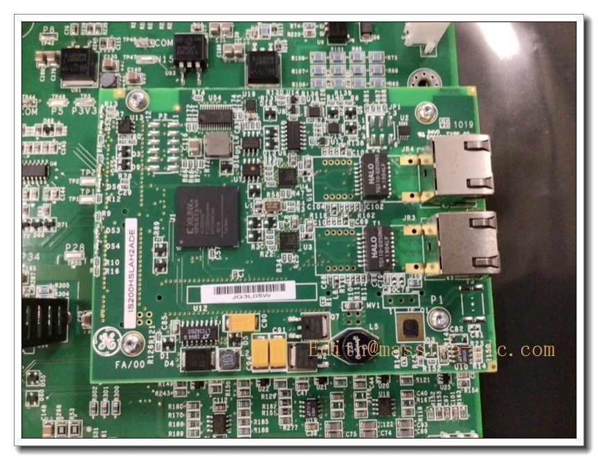
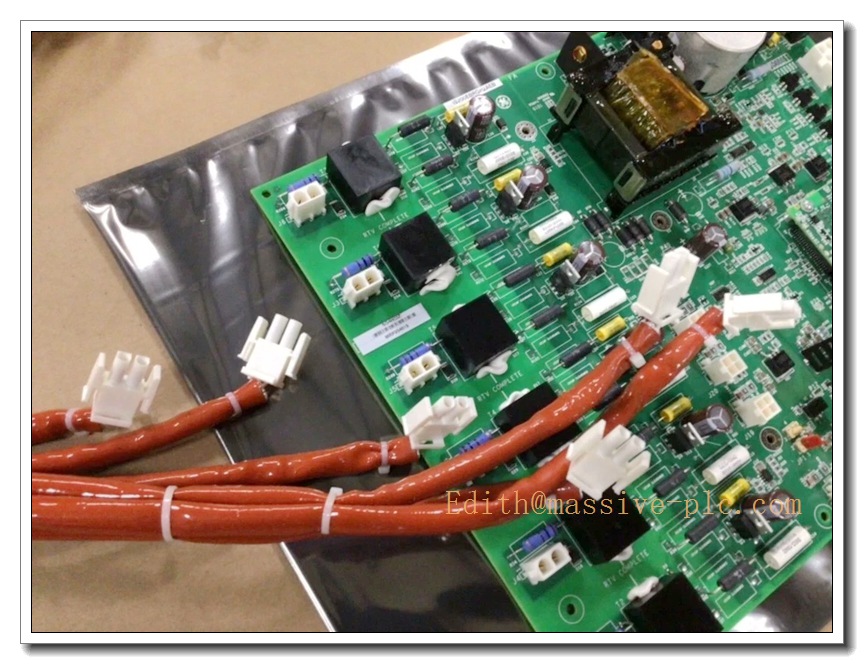
Description
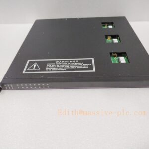
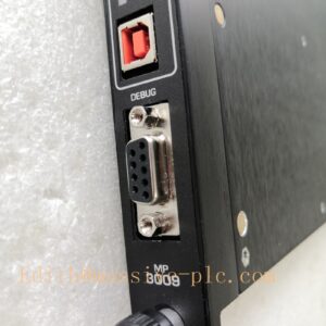
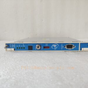
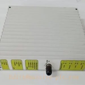
GE IS200EBRGH2A Exciter Bridge Interface Board (EBRG) for EX2100e / Mark VIe Generator Excitation System
Product Overview
The GE IS200EBRGH2A (EBRG) is a core exciter bridge interface PCB for the GE EX2100e excitation control platform under Mark VIe Speedtronic turbine control. It acts as the dedicated interface between the UCSB/PCM controller and the SCR thyristor power rectifier bridge. The board receives firing commands from the main controller, generates and distributes six SCR gate firing pulses, while continuously monitoring bridge health parameters including SCR temperature, cooling fan status, fuse integrity and bridge current via Rogowski coils. It supports simplex and redundant control topologies and is designed for 42 mm, 52 mm and 77 mm thyristor assemblies. This legacy board is discontinued by GE and only available as spare replacement for existing power plant excitation cabinets.
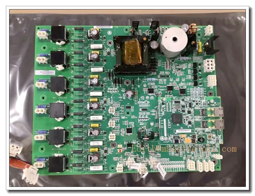
IS200EBRGH2A
Key Technical Specifications
- Part Number: IS200EBRGH2A
- Manufacturer: General Electric
- Board Type: EBRG Exciter Bridge Interface Board
- Compatible System: EX2100e / Mark VIe
- Gate Channels: 6 independent SCR gate pulse outputs
- Peak Gate Drive: 2 A, 24 VDC nominal pulse
- Pulse Width: 50–200 µs software configurable
- Input Logic: 5 V TTL command signals from system controller
- Main Board Supply: 125 VDC from station battery
- Auxiliary Power: Accepts 115 / 220 VAC 50/60 Hz for bridge auxiliary circuits
- Isolation Rating: 2500 Vrms between low-voltage control side and high-power gate circuits
- Supported Thyristor Sizes: 42 mm, 52 mm, 77 mm
- Onboard Monitoring: Thermistor temperature, cooling fan feedback, blown fuse detection, Rogowski coil current measurement
- Indicators: Multi-color LED status for gate supply, bridge temperature, fan, fault and pulse output
- Operating Temperature: 0°C ~ +60°C
- Storage Temperature: -40°C ~ +85°C
- Humidity: 5%–95% non-condensing
- Mechanical: Conformal coated PCB, rack mounted inside power conversion cabinet
- Weight: ~0.75 kg
Recommended 8 Similar Series Models (Mark VIe / EX2100e Family)
- GE IS200EBRGH1A (H1 revision, for 100 mm thyristors)
- GE IS200UCSBH1A UCSB Controller Board EX2100e
- GE IS200PCMH1B PCM Processor Control Module
- GE IS200EGPAG1BEC EGPA Gate Pulse Amplifier (previous model)
- GE IS200ERIOH1B Excitation I/O Board
- GE IS200FCTAH1A Field Current Transducer Board
- GE IS200TREGH1A Regulator Board
- GE IS200DSPX1H DSP Processor Board Mark VIe
Quality Control & Test Standard Operating Procedure (SOP)
- Visual Inspection: Inspect conformal coated PCB, pulse transformers, capacitors, terminal connectors and printed part marking. Check for burnt traces, corrosion, cracked solder joints or damaged pins. Confirm hardware revision matches documentation.
- Continuity & Hipot Isolation Test: Perform pin continuity test for gate drive and power terminals. Apply hipot test to verify 2500 Vrms isolation between low-voltage control circuits and high-energy gate outputs.
- Power-Up Functional Test: Apply 125 VDC and auxiliary AC power gradually. Verify quiescent current, LED boot sequence, no overheating or abnormal component noise.
- Built-in Diagnostic Test: Execute onboard self-test routine. Validate fault detection for over-temperature, fan failure and blown fuse simulation.
- 6-Channel Gate Pulse Test: Inject TTL firing commands from signal source. Verify timing, peak current, amplitude and pulse width of each of the six gate drive outputs.
- Bridge Feedback Simulation: Simulate thermistor temperature, fan status and Rogowski coil current signals. Confirm accurate analogue measurement and alarm threshold triggering.
- Controller Interface Communication Test: Connect to UCSB/PCM controller. Verify reliable command reception and bridge status/fault feedback back to EX2100e regulator.
- Environmental Burn-in Test: Continuous powered burn-in at rated ambient temperature to screen early-life component failures.
- Final Recheck & Documentation: Repeat gate pulse and diagnostic tests after burn-in. Generate serial-number traceable test report before anti-static packaging and shipment.
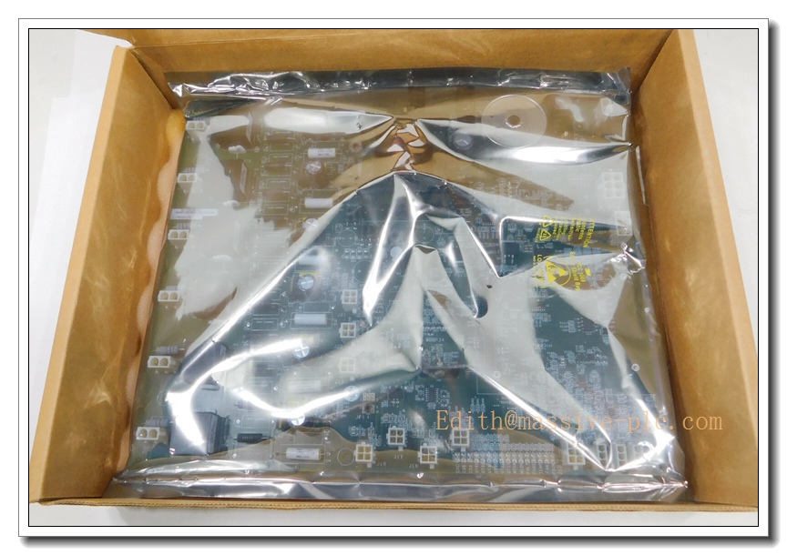
IS200EBRGH2A
New Module Installation Guide
- Pre-Install Preparation: Execute LOTO lockout-tagout procedure for excitation cabinet, power rectifier bridge and station 125 VDC battery supply. Wear ESD wrist strap and anti-static mat. Confirm part number and hardware revision match site BOM and thyristor size specification.
- Cabinet Slot Inspection: Inspect mating connectors, terminal blocks and wiring for oxidation, loose terminals or dust contamination.
- Board Mounting: Secure IS200EBRGH2A into the designated slot inside EX2100e power conversion cabinet. Fasten mounting screws evenly.
- Wiring Termination: Wire 125 VDC supply, auxiliary AC, UCSB control signal cable, six SCR gate cables and bridge sensor wiring following EX2100e schematic. Separate high-power gate cables from low-level control cables and implement proper shielding.
- Low-Power Energization: Restore only control power, keep high-voltage rectifier section de-energized. Check LED status and confirm no active hardware faults.
- Commissioning & Pulse Test: Launch EX2100e engineering tool, run system self-test. Perform simulated firing sequence to validate six-channel gate pulses and bridge monitoring feedback.
- Dry Run System Integration: Complete full excitation system dry run without generator field power. Confirm fault alarms are correctly reported to Mark VIe HMI.
- Post-Installation Documentation: Save system configuration file, record board serial number and commissioning test data in plant maintenance log.
Application Scenarios & Features
Application Scenarios
- EX2100e generator excitation cabinets for gas turbine and steam turbine power plants
- SCR thyristor bridge firing and health monitoring for synchronous generator field regulation
- Combined-cycle power generation Mark VIe turbine control systems
- Retrofit and spare replacement for legacy GE excitation power conversion cabinets
- Simplex and redundant excitation control architectures for large generators
Core Features
- 6-channel isolated SCR gate pulse generation for three-phase thyristor rectifier bridge
- Bidirectional interface: receives firing commands and returns comprehensive bridge health feedback
- Integrated multi-point bridge protection: over-temperature, cooling fan loss, blown fuse and over-current monitoring
- Supports 42/52/77mm thyristor stacks, compatible with simplex, warm backup and parallel bridge configurations
- Pulse transformers provide high galvanic isolation between control electronics and power thyristors
- Conformal coated PCB for dust, humidity and corrosive gas resistance inside power cabinets
- Onboard LED indicators for fast local troubleshooting of gate supply, temperature and fault conditions
- Native integration with EX2100e / Mark VIe excitation control ecosystem
FAQ
Q1: What is the difference between IS200EBRGH2A and IS200EBRGH1A?
A1: IS200EBRGH2A (H2) is designed for 77 mm and smaller thyristor assemblies. IS200EBRGH1A (H1) is for 100 mm thyristor stacks. Form factor is similar but internal power components and sensor scaling differ, not directly interchangeable without BOM validation.
Q2: What is the difference between EBRG and EGPA IS200EGPAG1BEC?
A2: EBRG () is the EX2100e Mark VIe bridge interface board, it generates gate pulses AND monitors bridge temperature/fan/fuse. EGPA is for older EX2100 Mark VI, only amplifies gate pulses with limited temperature monitoring. They belong to different generation excitation platforms.
Q3: Can I replace this board while excitation cabinet remains energized?
A3: Not recommended. This board connects to 125 VDC station battery and high energy SCR gate circuits. Perform full LOTO for both control power and high power bridge before removal and installation.
Q4: Is SIL certified?
A4: SIL rating applies to the complete excitation and turbine protection system, not standalone EBRG PCB. Full system safety assessment is required to achieve SIL compliance.
Q5: What sensors connect to the EBRG monitoring terminals?
A5: Thermistors for SCR heat sink temperature, cooling fan status switches, fuse blow indicators and Rogowski coils for bridge AC current measurement.
Q6: What will happen if EBRG detects bridge over-temperature?
A6: The board sends fault signal to UCSB/PCM controller. The EX2100e system triggers alarm and may initiate excitation trip based on system protection logic.
Q7: What maintenance and calibration interval is recommended?
A7: Annual visual inspection and functional pulse test; full bench calibration every 24 months, subject to power plant maintenance procedures and grid codes.
Q8: Is still manufactured by GE?
A8: GE has discontinued this legacy EX2100e Mark VIe EBRG board. Supplies are limited to new surplus and refurbished spare units for existing plant maintenance.