Description
EPRO PR6423/013-130 Eddy Current Probe with CON021 Signal Converter Complete Measurement Chain
Product Overview
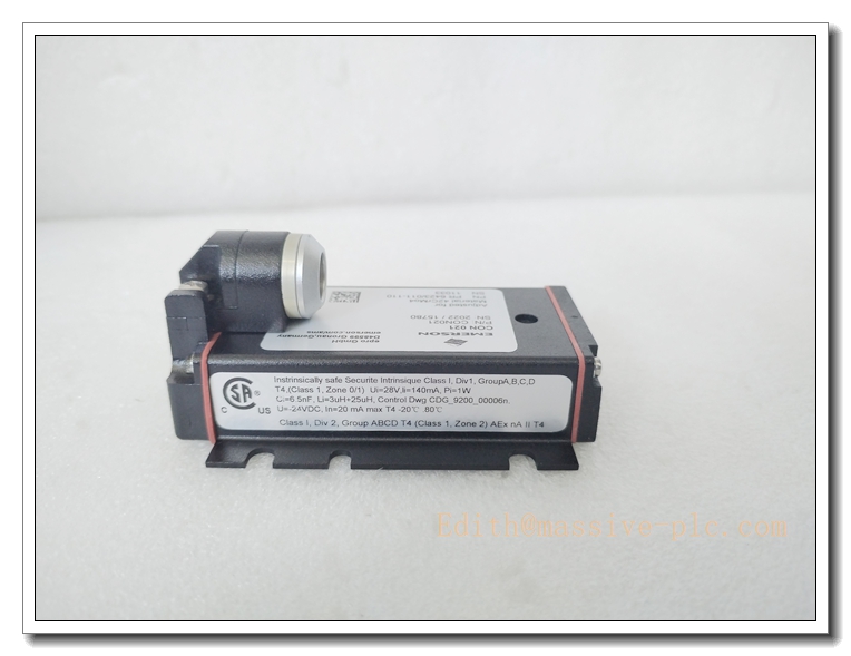
The PR6423/013-130 paired with CON021 forms a full eddy-current proximity sensor system originally from EPRO (now part of Emerson). This non-contact measuring chain captures shaft radial vibration, axial displacement, shaft position and eccentricity for high-speed rotating machinery. The PR6423/013-130 is the 8mm eddy current probe with integrated extension cable, while CON021 acts as the signal conditioning converter. It converts the probe’s raw eddy current signal into standard analogue voltage output, and provides built-in sensor fault diagnostics. This matched pair is factory calibrated together and widely interfaced to Meggitt VM600 (MPC4 / CMC16) and EPRO MMS machinery protection racks for turbine & compressor protection and condition monitoring.
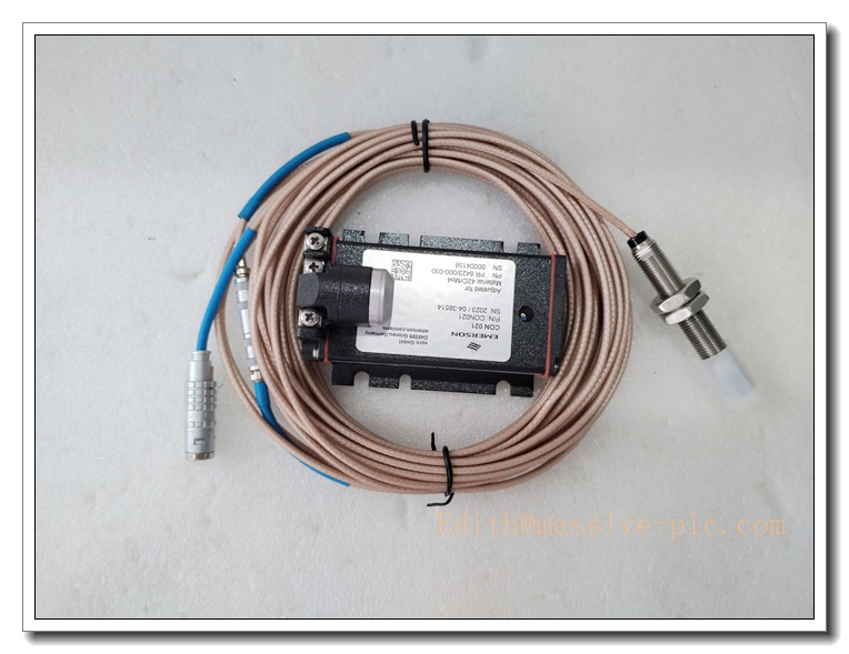
PR6423/013-130+CON021
Key Technical Specifications
- Assembly: PR6423/013-130 Probe + CON021 Signal Converter
- Measuring Principle: Eddy current, non-contact displacement measurement
- Probe Diameter: 8 mm
- Linear Measuring Range: ±1 mm (2 mm total linear span)
- Sensitivity: 8 V/mm
- Frequency Response: DC ~ 20 kHz
- Target Material: Calibrated for 42CrMo4 / SAE4140 steel
- Probe Operating Temp: -35°C ~ +180°C
- CON021 Converter Operating Temp: -20°C ~ +70°C
- Power Supply for CON021: -24 VDC (range -23 VDC ~ -32 VDC)
- Analogue Output: -4 VDC ~ -20 VDC
- Diagnostics: Cable break, short-circuit and probe fault detection, OK status relay
- Mounting: Probe threaded mounting; DIN rail / panel mount
- Protection Class: Probe IP67; IP20
- Cable: Integrated PTFE shielded extension cable for high temperature & oil resistance
- Linearity Error: ≤ ±1% full scale
Recommended 8 Similar Series Models
- PR6423/003-130 + CON021
- PR6423/010-130 + CON021
- PR6423/013-030 + CON021
- PR6424/010-040 + CON021 (16mm probe)
- PR6425/010-100 + CON011
- PR6423/013-130 + CON011
- PR6426/000-131 + CON041
- PR6423/13R-131 + CON021
Quality Control & Test Standard Operating Procedure (SOP)
- Visual Inspection: Check probe tip, stainless housing, cable insulation, Lemo connector and casing. Verify part marking and calibration certificate match the matched sensor set; inspect for cracks, oil contamination or connector damage.
- Continuity & Insulation Test: Test continuity of inner conductor and shield. Perform insulation resistance test between signal core and shield to detect cable leakage.
- Power Supply Test: Apply -24VDC to , confirm quiescent current within specification, no overheating.
- Static Calibration Test: Use calibrated target gap micrometer to set defined air gaps across full linear range. Record output voltage at each gap point, validate 8V/mm sensitivity and linearity.
- Fault Simulation Test: Simulate cable open and short circuit, confirm triggers fault status and OK relay changes state correctly.
- Dynamic Signal Test: Apply dynamic vibration displacement signal, verify frequency response and waveform fidelity up to 20 kHz.
- Interface Compatibility Test: Connect output to VM600 CMC16 / MPC4 card, confirm signal acquisition and channel fault reporting work properly.
- Burn-in Screening: Continuous powered burn-in at rated ambient temperature to eliminate early component failures.
- Final Recheck & Documentation: Repeat static calibration. Generate serial-number traceable calibration report before anti-static packaging.
New Module / Probe Installation Guide
- Pre-Install Preparation: Lock out / tag out rotating equipment. Wear ESD protection. Confirm the matched /013-130 + pair and calibration certificate; never mix unmatched probe/converter sets.
- Probe Mechanical Mounting: Install probe into the bearing housing threaded boss. Adjust probe air gap to midpoint of linear range (typically 1 mm gap). Lock the lock nut firmly. Ensure probe tip is perpendicular to shaft target surface.
- Cable Routing: Route the shielded extension cable, avoid sharp edges, high-temperature zones and high-current power cables. Single-point grounding for cable shield; do not double ground.
- Mounting & Wiring: Mount on DIN rail inside control cabinet. Wire -24VDC power, probe Lemo connector, analogue output and fault relay terminals following wiring diagram.
- Gap Verification: Power , measure output voltage to confirm installed gap value is within linear zone. Adjust probe position if required.
- System Commissioning: Connect analogue output to VM600 MPC4 / CMC16 input channel. Configure channel sensitivity 8 V/mm in monitoring software.
- Channel Test: Perform gap step test, confirm readings change linearly. Run sensor wire-break diagnostic test to verify fault detection function.
- Post-Installation Record: Save gap value, wiring check and calibration data into site commissioning log.
Application Scenarios & Features
Application Scenarios
- Steam turbine & gas turbine shaft vibration and axial thrust position monitoring
- Centrifugal compressors in petrochemical, refinery and LNG plants
- Turbo-generator sets for power generation machinery protection
- Critical high-speed pumps, gearboxes and blowers
- Rotor eccentricity, shaft orbit and slow-roll measurement
- Integration with Meggitt VM600 MPC4 / CMC16 rack systems and EPRO MMS series
Core Features
- Non-contact eddy current measurement, no mechanical wear between probe and shaft
- Complete matched calibrated pair: probe + extension cable + converter
- Wide operating temperature for bearing box high-temperature environments
- Built-in cable break / short circuit diagnostics for machinery protection safety chain
- 8 V/mm high sensitivity for precise micro-displacement measurement
- Analogue voltage output compatible with most TSI and machinery monitoring systems
- PTFE insulated cable, resistant to oil, chemical and thermal ageing
- Certified measurement chain for SIL capable protection systems (system-level assessment required)
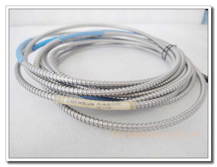
PR6423/013-130+CON021
FAQ
Q1: Can I use /013-130 probe with a different unit?
A1: Not recommended. The probe and converter are factory calibrated as one matched set. Mismatched pairs will create sensitivity and linearity error. Always use the original matched pair with calibration certificate.
Q2: What is the correct target material for this probe?
A2: Designed for 42CrMo4 / SAE4140 steel. Other steel grades or non-ferrous metal will alter sensitivity and calibration.
Q3: What happens when the probe cable is broken?
A3: will detect cable break, change the OK relay state and send a fault signal to VM600 MPC4/CMC16 for system alarm.
Q4: What is the recommended probe air gap setting?
A4: Set gap at approximately 1 mm (mid-range of ±1mm linear span). Verify via output voltage after installation.
Q5: Can this sensor be used with VM600 CMC16 / MPC4?
A5: Yes, the -4~-20V analogue output can be directly wired to or analogue input channels. Set channel sensitivity to 8 V/mm in software.
Q6: What is the calibration interval?
A6: Recommended recalibration every 12–24 months, subject to site safety and API 670 requirements.
Q7: Can I shorten or splice the integrated extension cable?
A7: Do not splice or cut the factory integral cable. Cable length is part of the factory calibration; modification invalidates calibration and causes measurement drift.
Q8: Is the + SIL rated?
A8: SIL rating applies to the complete protection measurement chain including probe, converter, monitoring card and logic solver. The single sensor pair itself is not standalone SIL certified.