
Description
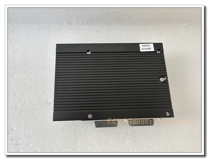
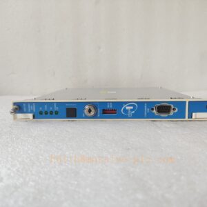
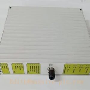
D201138 Industrial PCB Control Board Assembly
Product Description
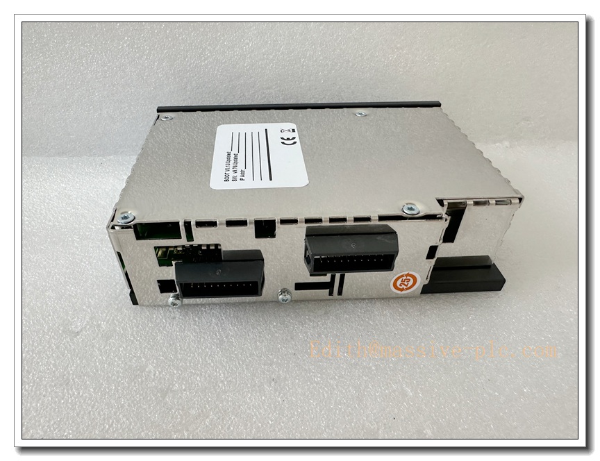
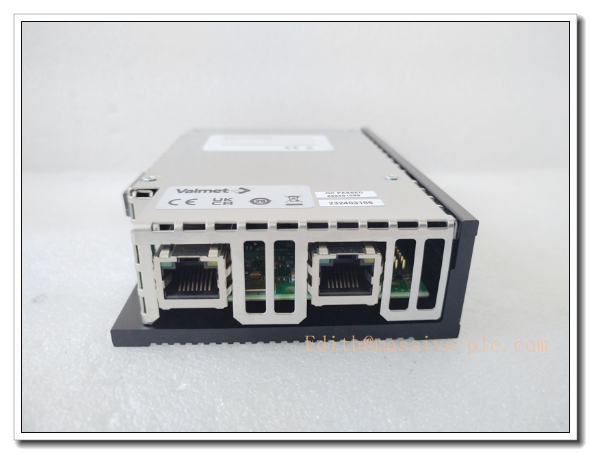
The D201138 is a heavy-duty OEM printed circuit board assembly designed as a direct replacement spare for industrial machinery control systems. It functions as an on-site signal conditioning and I/O interface board, mediating signal exchange between the main controller, field sensors, proximity switches, solenoid actuators and local terminal blocks. The board samples digital status signals, buffers output commands and communicates status data back to the master controller via the internal system bus. Constructed to withstand continuous cabinet operation with mechanical vibration, electrical noise and moderate thermal cycling, it supports round-the-clock operation for automated production equipment and legacy machine platforms. It is a critical service spare to minimize production downtime during board failure.
D201138L
Technical Specifications
| Item | Parameter |
|---|---|
| Model | D201138 |
| Type | PCB control board assembly, OEM spare part |
| Signal Type | Digital input and output signal conditioning |
| Operating Temperature | 0°C ~ +60°C |
| Storage Temperature | -40°C ~ +85°C |
| Supply Voltage | 24 VDC nominal |
| Isolation | Partial galvanic isolation for field I/O channels |
| Mounting | Fixed mounting inside equipment cabinet with spacers and screws |
| Environmental Requirement | Indoor cabinet installation, non-condensing atmosphere |
| Communication | On-board internal bus for host controller data exchange |
Compatibility & Installation Traps
Compatibility
- Dedicated replacement board for the matching original machine control assembly.
- Compatible with original wiring harnesses, terminal connectors and factory-approved firmware of the target machine.
- Hardware revision verification is mandatory. Mismatched main CPU firmware or controller revisions will cause detection failure or abnormal I/O behavior.
- Visually similar circuit boards are not interchangeable without confirmation of full part number and revision level.
Common Installation Traps
- Neglecting revision check before replacement; mismatched revisions lead to boot failure or intermittent channel faults.
- Handling bare PCB without ESD protection, resulting in hidden electrostatic damage to semiconductors.
- Reusing aged, corroded connectors without inspection, which causes unstable and intermittent signal loss.
- Reversed power polarity during wiring, which will destroy the on-board power regulation circuit instantly.
- Mounting the board in poorly ventilated cabinet areas; prolonged overheating leads to drift and premature component failure.
- Mixing low-voltage signal terminals with high-power terminals, triggering short circuits and permanent board burnout.
- Hot-swapping the board while the control system is energized.
- Retaining outdated configuration files after replacement, causing I/O mapping conflicts and incorrect logic execution.
Standard Operating Procedure (SOP)
- Pre-inspection: Inspect the D201138 board for physical damage, displaced components or deformed connectors. Confirm the part number and revision match the faulty original board.
- Lockout and isolation: Shut down the entire machine, isolate main power and verify zero voltage on board terminals with a multimeter.
- ESD preparation: Wear an ESD wrist strap and use an anti-static mat during all handling steps.
- Disassembly: Label all wiring connections before unplugging harnesses. Remove mounting fasteners and spacers, then carefully extract the defective board.
- Board mounting: Align the new D201138 board with mounting holes, fit spacers and fasten screws evenly.
- Wiring restoration: Reconnect harnesses following pre-marked labels; double-check power polarity, signal routing and ground connections.
- Power-up and hardware recognition: Restore power gradually, boot the host controller and wait for automatic hardware identification.
- Configuration and functional test: Load the validated system configuration, perform point-to-point I/O testing and simulate field signals to confirm full functionality.
- Final handover: Record the serial number and revision of the replacement board, clear historical fault logs and return the machine to normal production operation.
D201138L
Application Scenarios
- OEM automation machine control cabinet spare replacement
- Automated material handling and conveyor control subsystems
- Packaging, forming and web converting machinery digital I/O control
- Hydraulic and pneumatic equipment signal interface
- Assembly line automatic testing stations
- Metalworking and fabrication machinery control subsystems
- Textile and continuous-process automation equipment
- Legacy industrial equipment maintenance and retrofit
Matching Components
- Original machine controller chassis and backplane assembly
- 24 VDC regulated industrial power supply unit
- Matching wiring harnesses and terminal connector kits
- ESD wrist strap and anti-static workstation mat
- Mounting spacers, screws and lock washers
- Host CPU module and qualified firmware package
- Signal terminal blocks and cable strain relief hardware
- Cabinet cooling fans and thermal monitoring components
Recommended Related Models (8)
- D201130
- D201132
- D201134
- D201136
- D201139
- D201140
- D201142
- D201144


 Start Chat




