
Description
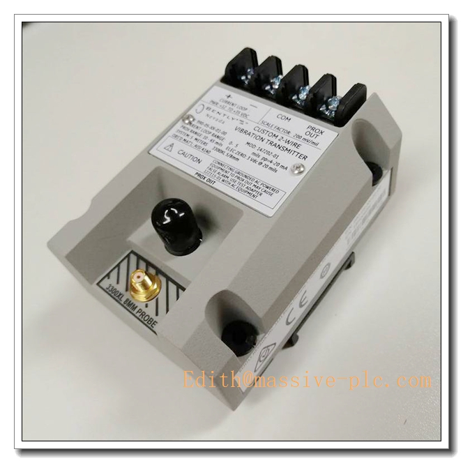
Bently Nevada 990‑05‑50‑01‑00 — Vibration Transmitter
Product Overview
The 990‑05‑50‑01‑00 is a compact two‑wire loop‑powered vibration transmitter from Bently Nevada 990 series. It interfaces with 3300‑XL 8 mm eddy‑current proximity probe systems to measure shaft relative vibration and displacement. The unit converts raw proximity transducer signal into standardized 4‑20 mA analog output for PLC, DCS or SCADA host systems. Compliant with common industrial rotating‑machinery monitoring requirements, it is widely used for local machinery protection and predictive maintenance where full rack‑based monitor system is not required.
Critical Compatibility Warning
- Designed for 3300‑XL 8 mm proximity probe transducer system. Total transducer cable length (probe pigtail + extension cable) shall be 5 meters for this 990‑05‑50‑01‑00 model.
- Not compatible with 11 mm probe series or NSv transducer family.
- 4‑20 mA output corresponds to configured vibration measurement range; this transmitter does not support direct connection to 3500 rack system.
- Requires 2‑wire loop power supply. Incorrect total transducer cable length will cause scale‑factor error and inaccurate readings.
Part Number Decoding
- 990:Series of two‑wire vibration transmitter
- ‑05:Supported total transducer cable length = 5 m
- ‑50:Measurement range: 0‑50 μm peak‑to‑peak vibration
- ‑01:Output function: Vibration (displacement peak‑to‑peak)
- ‑00:Standard non‑intrinsically‑safe version, no hazardous‑area certification
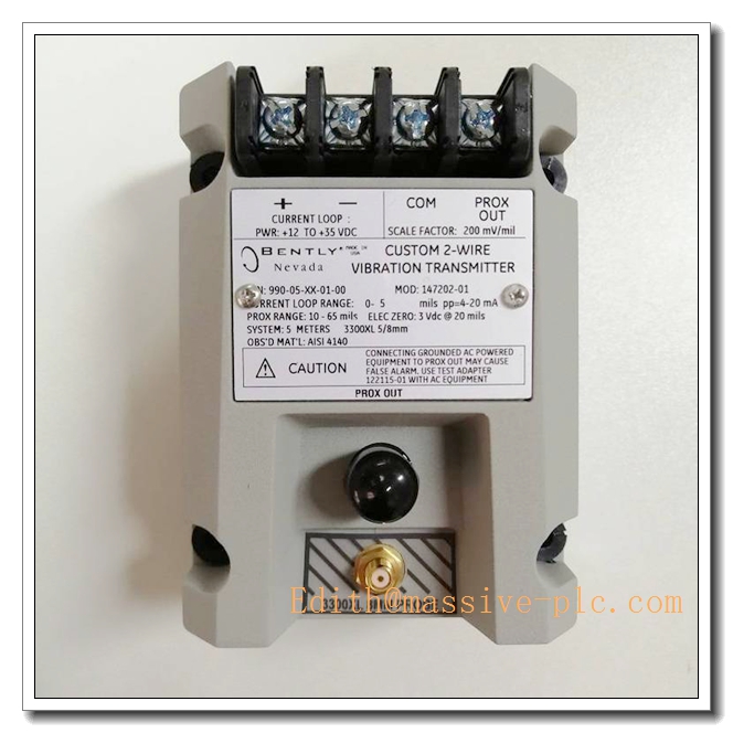
990-05-50-01-00
Key Specifications
| Parameter | Value |
|---|---|
| Part Number | 990‑05‑50‑01‑00 |
| Series | 990 Two‑Wire Vibration Transmitter |
| Supported Transducer | 3300‑XL 8 mm Eddy‑current Proximity Transducer |
| Total Transducer Cable Length Requirement | 5 m (fixed) |
| Measurement Parameter | Shaft relative vibration (peak‑to‑peak displacement) |
| Measuring Range | 0‑50 μm peak‑to‑peak |
| Analog Output | 4‑20 mA loop‑powered output |
| Frequency Response | 10 Hz ~ 1 kHz |
| Power Supply | 18‑30 VDC two‑wire loop power |
| Load Resistance | Max 500 Ω |
| Enclosure | DIN‑rail mount compact housing |
| Mounting | Standard DIN‑rail EN 60715 |
| Operating Temperature Range | ‑40 °C ~ +85 °C |
| Certifications | Standard industrial version, non‑IS, without ATEX / IECEx approvals |
| Housing Material | Plastic industrial enclosure |
| Country of Origin | USA |
| Weight | ≈0.18 kg |
Main Features
- Two‑wire loop‑powered design: Simplifies field wiring, only two conductors for both power supply and analog signal output.
- Fixed 5 m transducer cable matching: Optimized to work with 3300‑XL 8 mm proximity transducer system with exact 5 m total cable length.
- 0‑50 μm peak‑to‑peak vibration measurement range: Suitable for small‑to‑medium rotating equipment such as pumps, fans and blowers.
- Standard 4‑20 mA industry‑standard output: Seamless integration with PLC, DCS and general‑purpose data acquisition systems without special monitor rack hardware.
- Wide frequency response 10 Hz‑1 kHz: Covers most typical rotational speed vibration frequencies for general industrial rotating machinery.
- DIN‑rail mounting form factor: Easy installation inside control cabinets and local junction boxes.
- Non‑intrinsically‑safe standard unit: Cost‑effective solution for safe‑area condition‑monitoring applications.
Typical Application Scenarios
- Relative shaft vibration monitoring for pumps, fans, blowers and small compressors without full 3500 rack‑based monitoring system
- Retrofit upgrade of existing 3300‑XL proximity probe installations to provide 4‑20 mA signal to DCS / PLC
- Auxiliary condition‑monitoring points for auxiliary rotating equipment in power plants, water treatment plants and general manufacturing facilities
- Cost‑effective predictive‑maintenance point deployment where high‑density rack monitor is not economically justified
- Spare‑part replacement for existing 990 series transmitters in non‑hazardous‑area industrial sites
Related & Recommended Alternative Models
| Model | Description |
|---|---|
| 990‑05‑100‑01‑00 | 990 transmitter,5 m cable,0‑100 μm p‑p vibration,non‑IS |
| 990‑08‑50‑01‑00 | 990 transmitter,8 m cable,0‑50 μm p‑p vibration,non‑IS |
| 990‑05‑50‑01‑05 | 990 transmitter,5 m cable,0‑50 μm p‑p vibration, IS‑certified for hazardous zones |
| 330103‑00‑xx‑xx‑xx‑xx | 3300‑XL 8 mm proximity probes |
| 330130‑xx‑xx‑00 | 3300‑XL extension cables for building‑up exact 5 m total transducer length |
Compatible Components & Accessories
- 3300‑XL 8 mm proximity probe: 330101 / 330103 /330105 /330905 /330907 series probes
- Extension cables: 330130 series Microdot / ClickLoc extension cables to achieve exact total 5 m transducer length
- Power supply: 18‑30 VDC DC power source for two‑wire loop
- Acquisition host: PLC / DCS / SCADA analog input module (4‑20 mA)
- Mounting accessories: Standard DIN‑rail, cabinet mounting clips, cable glands
- Calibration fixture: 8 mm proximity probe static gap calibration rig for pre‑commissioning validation
Installation and Configuration Guide
Warning: Installation must be performed by qualified instrumentation technicians. Always refer to original Bently Nevada 990 series official manual as primary reference document. This non‑IS transmitter shall NOT be installed within explosive hazardous classified zones.
- Transducer Loop Assembly
- Sum probe integral pigtail length plus extension cable length must equal exact 5 meters. Any deviation will introduce measurement error.
- Route proximity transducer coaxial cable separately from high‑power AC cables to minimize EMI interference. Observe minimum bending radius of coaxial cable.
- Make secure connector mating, apply specified torque for Microdot / ClickLoc connectors; do not force pin alignment.
- DIN‑Rail Mounting & Power Wiring
- Snap the transmitter onto standard DIN‑rail inside non‑hazardous control cabinet.
- Perform two‑wire loop wiring: connect 18‑30 VDC power supply in series with transmitter and analog input module. Observe polarity marking on terminal block.
- Do not apply external separate voltage directly across transmitter signal terminals.
- System Commissioning & Calibration
- Confirm mechanical probe gap setting to target operating gap (normally ~1.27 mm for 8 mm probe).
- Power on the loop supply. Verify 4‑20 mA output behaviour.
- Perform static gap test with calibration fixture to validate measurement output.
- Confirm no fault indication; cross‑check 4‑20 mA reading against reference gap value.
- Maintenance & Troubleshooting
- Inspect transducer connectors for dirt, oil contamination and corrosion during equipment shutdown.
- Check coaxial cable for abrasion, crush and ageing damage.
- Abnormal fixed‑value output or non‑linear reading often points to wrong total transducer cable length, damaged probe or bad connector contact. Replace defective components; field repair of proximity coaxial cable is not allowed.
- Special Installation Restriction
- Model 990‑05‑50‑01‑00 is non‑intrinsically‑safe variant. Only deploy within non‑hazardous safe‑area cabinets.
Supplementary Remark
990‑05‑50‑01‑00 is Bently Nevada 990‑series two‑wire loop‑powered vibration transmitter for 3300‑XL 8 mm proximity transducer system with fixed 5 m total cable length, measuring 0‑50 μm peak‑to‑peak shaft relative vibration and outputting standard 4‑20 mA signal. This non‑IS unit is intended for safe‑area installation only. Before commissioning, strictly verify total transducer cable length equals 5 m, cross‑check part‑number, measuring range and non‑IS property versus project BOM and technical drawings.



 Start Chat




