
Description
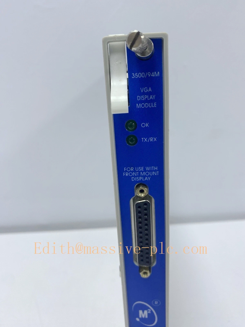
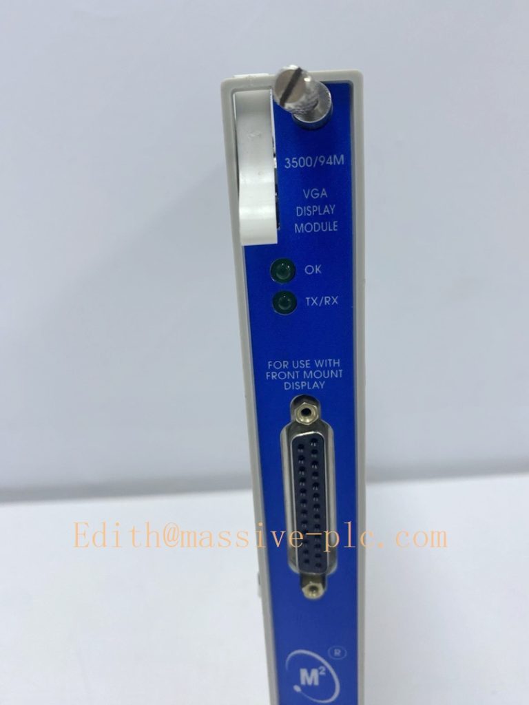
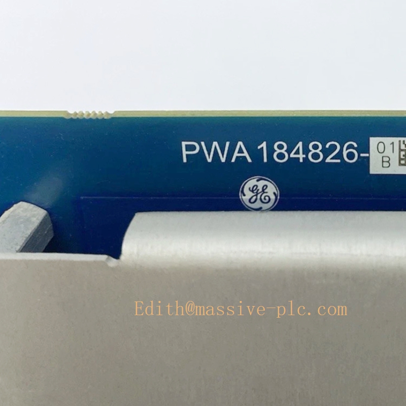
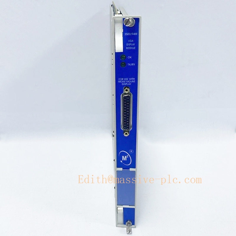
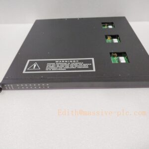
Bently Nevada 3500/94M (184826‑01) VGA Display Main Module
184826‑01
Model Introduction
Model: 3500/94M VGA Display Main Module Part Number: 184826‑01 Device Type: Single‑slot rack‑insert graphic display main module for 3500 machinery‑protection rack, provides VGA graphic output & touch‑screen control interface. Manufacturer: Bently Nevada (Baker Hughes) System Compatibility: Installed in any full‑size 3500 rack user slot; must work with 3500/22 TDI Transient Data Interface module. Needs matching rear I/O module: 190214‑01 (Normal I/O) or 190214‑02 (Power‑only I/O). Not compatible with mini‑rack. Not a Modbus gateway. Cannot be mixed‑used with 3500/94 (145988‑01) communication module, different hardware function. Application Scenarios: TSI turbine supervisory instrumentation, power plant, oil‑gas compressor machinery‑protection systems. Output VGA signal to external industrial touch‑display, provides local graphical HMI for real‑time vibration, displacement, speed, temperature, alarm status, event log. Supports VNC remote desktop access. Complies with API‑670 standard. Country of Origin: United States Lifecycle Status: Obsolete OEM production, only aftermarket spare‑part supply available.
Important note: ‑ 184826‑01: 3500/94M main front module (inside rack) ‑ 190214‑01 / 190214‑02: Corresponding rear I/O card ‑ External: 10‑inch /15‑inch industrial VGA touch‑screen display (customer‑supplied or optional accessory) ‑ 3500/94M is graphic display system, NOT serial‑Ethernet gateway. It cannot output Modbus‑RTU/TCP to DCS/PLC. For Modbus communication use 3500/91 /91M /92. ‑ Distinction: 3500/94 (145988‑01) = Ethernet‑serial bridge; 3500/94M (184826‑01) = VGA graphic display main module, two completely different hardware.
Technical Introduction
Core Functions
‑ Acquire full rack measurement & alarm data via 3500 proprietary backplane bus, relies on 3500/22 TDI for high‑speed data transmission. ‑ VGA video output for external industrial monitor/touch‑screen. ‑ RS‑232 touch‑controller interface for touch‑screen operation control. ‑ Embedded VNC server, supports remote graphic view over network. ‑ Support up to nine user‑configurable display pages via 3500 Rack Configuration Software. ‑ Front‑panel 24 VDC power supply output for front‑mount display. ‑ On‑board self‑diagnostics, report module faults into rack system event log.
Key Technical Specifications
| Item | Parameter |
|---|---|
| Video Interface | VGA output (DB25 front‑edge connector) |
| Touch Interface | RS‑232 for touch‑screen controller |
| Rack Bus | 3500 proprietary backplane; requires 3500/22 TDI |
| Mating Rear‑I/O | 190214‑01 (Normal I/O) / 190214‑02 (Power‑only I/O) |
| Power Supply | Powered by 3500 rack backplane 24 VDC |
| Power Consumption | 4.6 W typical |
| Operating Temperature | ‑20 ℃ ~ +65 ℃ |
| Storage Temperature | ‑40 ℃ ~ +85 ℃ |
| Humidity | 5 %‑95 % non‑condensing |
| Dimension | Standard single‑slot full‑height 3500 rack module |
| Weight | 0.73 kg |
| Compliance | API‑670, Class I Div2 hazardous‑area certification, EMC EN61000‑6‑2 /‑6‑4 |
Mechanical Feature
Single‑slot hot‑swappable front‑insert module. Must pair with dedicated rear‑I/O card (190214‑01 / 190214‑02). Front‑side DB25 edge‑connector integrates VGA, RS‑232 touch and 24 VDC power output. Max cable distance to external display approx 20 ft (6.1 m). Hot‑swap supported under rack powered‑on condition, follow official maintenance procedure.
184826‑01
Adaptive Quality Assurance & Test Protocol
3.1 Factory Adaptive QA Procedure
- Backplane bus continuity test: Verify signal integrity between module connector and rack backplane, detect open‑circuit / short‑circuit defects.
- VGA video output test: Verify graphic resolution, signal stability with compatible industrial monitor.
- RS‑232 touch‑port interoperability test: Touch‑screen command receiving & response test.
- Data synchronization test: Pair with 3500/22 TDI module; verify real‑time channel value, alarm status, event‑list forwarding.
- Configuration download test: Download rack configuration via 3500 Rack Configuration Software; confirm custom display‑page loading.
- VNC remote‑access function test.
- Fault‑simulation test: Simulate display cable break, TDI communication loss; verify fault codes logged into rack event log.
- Environmental screening: Temperature cycling test, EMC noise‑immunity test.
- Built‑in self‑diagnostic execution; serial‑number traceability, full functional‑test report archived.
3.2 On‑site Acceptance Test Protocol
- Visual inspection: Check module physical integrity, front DB25 connector pins without damage or oxidation.
- Rack installation test: Insert 184826‑01 into any user‑slot of full‑size 3500 rack; install matched rear‑I/O card 190214‑01/02; ensure 3500/22 TDI is present in rack; power‑on, connect via configuration software, confirm no hardware mismatch alarms.
- Display‑wiring test: Connect VGA cable, RS‑232 touch cable between 3500/94M front‑connector and external touch‑screen monitor.
- Power‑on test: Confirm module OK / TX‑RX LED status normal; external monitor outputs graphic page.
- Data‑consistency cross‑check: Compare display readings against 3500 Rack Configuration Software online values.
- Alarm‑simulation test: Trigger channel alert/danger; verify alarm information shows on graphic display.
- Touch‑screen functional test: Operate menu navigation via touch panel.
- VNC remote‑view test: Establish VNC connection from host PC, verify remote graphic mirroring.
- Communication‑break simulation: Disconnect/reconnect display cable; verify fault reporting and auto‑recovery.
- Test‑record filing: Log part‑number, hardware revision, firmware version, test‑result snapshot for site QA archive.
Field Engineer Technical Notes
Installation Guidance
‑ Slot rule: 3500/94M 184826‑01 can be installed in any user‑slot of full‑size 3500 rack. Rack must contain 3500/22 TDI module, otherwise 3500/94M cannot work. Not compatible with mini‑rack. ‑ Must install corresponding rear‑I/O card: 190214‑01 or 190214‑02. Front‑module and rear‑I/O card are one set, cannot run without rear‑card. ‑ Front‑DB25 wiring: VGA video, RS‑232 touch signal, 24 VDC power output for display. Keep total cable length ≤20 ft for stable video & touch signal. ‑ Critical distinction: This is graphic local‑display module. No Modbus‑RTU / Modbus‑TCP output. For DCS/PLC integration, you still need independent gateway module (3500/91 /91M /92).
Field note: 184826‑01 is obsolete legacy hardware. Spare‑parts are limited to aftermarket inventory. Many sites replace 3500/94M solution with PC‑based System 1 monitoring software.
Commissioning Tips
‑ After full set hardware installation (184826‑01 + rear‑I/O + 3500/22 TDI), download complete rack configuration. Configure custom graphic display pages inside 3500 Rack Configuration Software. ‑ Confirm VNC‑server setting, network access permission. ‑ Cross‑validate: channel‑value, alarm‑status, event‑list must keep consistent between graphic display and configuration‑software.
Troubleshooting Common Issues
- Module not recognized: Confirm 3500/22 TDI module exists in rack; check front‑module and rear‑I/O card seating; check backplane connector contact.
- External monitor no picture: Check DB25 cable integrity, VGA wiring definition, display power supply.
- Touch‑screen no response: Verify RS‑232 touch‑cable wiring, baud‑rate parameter matching.
- Partial‑channel missing on graphic pages: Re‑download rack configuration, confirm all monitor modules are healthy.
- VNC cannot connect: Check network‑firewall setting, VNC‑server enable status inside rack configuration.
Diagnostic reference: Read rack system event‑log inside 3500 Rack Configuration Software for 3500/94M fault codes.
Maintenance & Spare‑part Recommendation
‑ No user‑serviceable components onboard; replace complete 184826‑01 front‑module plus corresponding rear‑I/O card upon hardware failure. ‑ Spare‑part suggestion: Maintain matched full‑set: 184826‑01 + 190214‑01/02 for legacy racks using 3500/94M graphic display. For new spare‑procurement, evaluate migration to PC‑monitoring solution to avoid obsolete‑hardware risk. ‑ Preventive inspection during shutdown: Check front‑side DB25 connector tightness, rear‑I/O card seating, cable aging and shielding integrity.
184826‑01
3500 Display‑related Module Family Comparison Table
| Part Number | Module Type | Rear‑I/O Card | Key Requirement | Main Function |
|---|---|---|---|---|
| 184826‑01 (3500/94M) | VGA Graphic Display Main Module | 190214‑01 / 190214‑02 | Requires 3500/22 TDI | VGA graphic output + VNC remote view, NO Modbus |
| 145988‑01 (3500/94) | Ethernet‑Serial Bridge | None | No special module required | Bently proprietary protocol Ethernet‑serial, NO Modbus |
| 135799‑01 (3500/93 DIM) | Display‑Interface Module | None | Install in slot‑15 only | RS‑485 for 3500/93 text‑display panel |
| 135785‑02C | 3500/93 backlight text‑display unit | External panel | Pair with 135799‑01 DIM | Text‑based local operator panel |


 Start Chat




