
Description
Bently Nevada 3500/93 (135799‑01) Display Interface Module (DIM)
Model Introduction
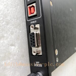
Model: 3500/93 Display Interface Module (DIM) Part Number: 135799‑01 Device Type: Front‑slot rack‑mount display interface module, dedicated communication bridge between 3500 rack and 3500 system display unit. Manufacturer: Bently Nevada (Baker Hughes) System Compatibility: Installed in slot‑15 (right‑most slot) of full‑size 3500 rack; works together with external 3500/93 System Display Unit. No dedicated separate rear‑I/O card, it uses rack internal backplane, RS‑485 field port located on front module edge connector. Not compatible with 3500 mini‑rack. Cannot substitute for 3500/91 /91M /92 gateway modules. Application Scenarios: TSI turbine supervisory instrumentation, thermal‑power steam turbines, oil‑gas centrifugal compressors. Transmits rack real‑time measurement data, alarm status, event log to local/remote 3500/93 display panel for on‑site operator local visualization, complies with API‑670 standard. Country of Origin: United States Lifecycle Status: Legacy obsolete module, OEM discontinued; only aftermarket spare‑part support available.
Note: 135799‑01 is DIM (Display Interface Module) front board, it does NOT have matching separate rear‑I/O card. The 3500/93 system consists of two independent hardware parts: 135799‑01(DIM rack‑insert module) + external display panel unit. RS‑485 communication cable connects DIM front‑module port to display unit.
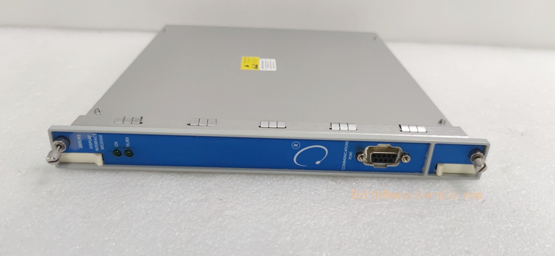
135799‑01
Technical Introduction
Core Functions
‑ Acquire full rack data via 3500 proprietary backplane bus: vibration, displacement, speed, temperature, channel status, alarm & trip status, system event list. ‑ Convert rack internal bus signal to RS‑485 differential signal for long‑distance communication to external 3500/93 display panel. ‑ Support multi‑mounting‑mode display connection: face‑mount on rack front, 19‑inch cabinet rack‑mount, remote panel‑mount (max 4000 feet RS‑485 distance). ‑ Process data forwarding for local display panel; not for DCS/PLC Modbus gateway function. Configuration downloaded via 3500 Rack Configuration Software. ‑ On‑board self‑diagnosis, report DIM communication failure and rack fault into system event log.
Key Technical Specifications
| Item | Parameter |
|---|---|
| Field Communication Interface | RS‑485 (front‑module edge connector, to display panel) |
| Rack Bus Interface | 3500 proprietary backplane bus (slot‑15 only) |
| Power Supply | Powered fully by 3500 rack backplane 24 VDC |
| Power Consumption | 3.5 W typical |
| Operating Temperature | ‑30 ℃ ~ +65 ℃ |
| Storage Temperature | ‑40 ℃ ~ +85 ℃ |
| Humidity | 5 %‑95 % non‑condensing |
| Dimension | Standard single‑slot front module for full‑size 3500 rack |
| Weight | 0.38 kg |
| Compliance | API‑670 compliant for machinery protection system; industrial EMC certification |
Mechanical Feature
Single‑slot front‑insert module, must occupy slot‑15 (right‑most slot) of full‑size 3500 rack. No corresponding rear‑I/O card; RS‑485 wiring is done on front‑side edge connector. Hot‑swap capable under rack powered‑on condition, follow official maintenance procedure. It only serves for local operator display panel, cannot output Modbus signal to DCS.
Adaptive Quality Assurance & Test Protocol
3.1 Factory Adaptive QA Procedure
- Backplane bus continuity test: Verify signal integrity between module connector and rack backplane, detect open‑circuit / short‑circuit defects.
- RS‑485 communication adaptive test: Verify baud‑rate stability, long‑distance signal simulation, noise immunity test.
- Data forwarding interoperability test: Pair with genuine 3500/93 display unit; validate real‑time measurement value transmission, alarm status sync, event‑list synchronization.
- Configuration download test: Download rack configuration via 3500 Rack Configuration Software; confirm DIM module correctly recognizes rack slot layout and monitor parameters.
- Fault simulation test: Simulate rack channel alarm, system trip, communication cable break; verify DIM correctly report fault codes into rack event log.
- Environmental screening: Temperature cycling test, EMC noise immunity test for RS‑485 port.
- Built‑in self‑diagnostic execution: Trigger module self‑test, check fault flag reporting.
- Serial‑number traceability, part‑number label verification, full functional‑test report archived.
3.2 On‑site Acceptance Test Protocol
- Visual inspection: Check front‑module physical integrity, connector pin condition, no mechanical damage or oxidation.
- Rack installation test: Install 135799‑01 into slot‑15 (right‑most slot) of full‑size 3500 rack; power‑on rack, connect via 3500 Rack Configuration Software, confirm no hardware mismatch alarms.
- Display unit communication test: Wire RS‑485 cable between DIM front‑port and 3500/93 display panel; confirm panel successfully synchronizes all channel real‑time data, alarm status and system event list.
- Alarm‑trigger simulation: Manually trigger channel alarm/trip on rack; verify alarm information synchronizes onto display panel without delay.
- Module self‑test execution: Launch module self‑test via configuration software; confirm zero critical faults inside rack system event‑log.
- Communication‑break simulation: Disconnect and reconnect RS‑485 display cable; verify module reports communication loss alarm, and auto‑recover data sync after cable reconnection.
- Test‑record filing: Log part‑number, hardware revision, firmware version, test‑result snapshot for site QA archive.
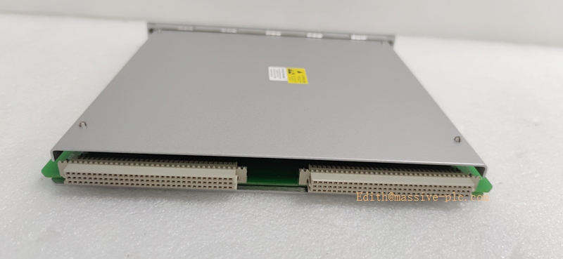
135799‑01
Field Engineer Technical Notes
Installation Guidance
‑ Mandatory slot rule: 135799‑01 DIM module must be inserted into slot‑15 (right‑most slot) of full‑size 3500 rack. Not functional in other slots; incompatible with mini‑rack system. ‑ No rear‑I/O card required; RS‑485 wiring connects to edge connector on front‑module face. ‑ Insert front‑module firmly into slot‑15, tighten locking screws to avoid intermittent poor‑contact faults. ‑ RS‑485 wiring: Use shielded twisted‑pair cable for connection to display panel; terminate bus terminal resistor as required; implement single‑end shield grounding, avoid multi‑point ground‑loops. ‑ Important distinction: This DIM module is NOT a Modbus gateway. It cannot output data to DCS/PLC. For DCS communication, you still need 3500/91 /91M /92 gateway module.
Field note: Since 135799‑01 is obsolete legacy hardware, spare‑part supply is limited. When DIM or display panel fails, many sites migrate to PC‑based monitoring software instead of physical 3500/93 display hardware.
Commissioning Tips
‑ After hardware installation, download complete rack configuration; 3500 software will automatically recognize DIM module in slot‑15. ‑ Confirm RS‑485 cable polarity, bus termination resistor setting for display communication link. ‑ Cross‑validate: compare display panel readings against rack local buffer output and configuration software readings. ‑ Verify alarm propagation: channel alarm, trip‑multiply, rack fault should be visible both in rack software and on 3500/93 display panel.
Troubleshooting Common Issues
- DIM module not recognized: Confirm module is installed strictly in slot‑15 (right‑most slot); check backplane connector integrity.
- Display panel no communication / blank screen: Check RS‑485 cable polarity, terminal resistor, cable integrity; inspect DIM front‑side communication status LED.
- Data mismatch / partial channel missing: Re‑download rack configuration; verify all monitor modules are healthy without channel hardware faults.
- Intermittent display communication dropout: Check cable shielding & grounding, eliminate ground‑loop interference; check RS‑485 bus terminal resistor setting.
Diagnostic reference: Read rack system event‑log inside 3500 configuration software for DIM communication fault codes.
Maintenance & Spare‑part Recommendation
‑ No user‑serviceable components onboard; replace complete 135799‑01 module upon hardware failure. ‑ Spare‑part suggestion: Maintain spare 135799‑01 for legacy racks with physical 3500/93 display unit. For new spare‑procurement, evaluate migration to PC‑monitoring solution to avoid obsolete hardware risk. ‑ Preventive inspection during shutdown: Check slot‑15 locking condition, RS‑485 front‑connector tightness, cable aging and shielding integrity.
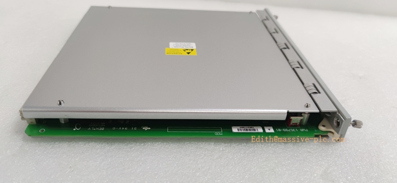
135799‑01
3500/93 vs Gateway Module Family Comparison Table
| Part Number | Module Type | Rack Slot Requirement | Rear‑I/O Card | Main Function |
|---|---|---|---|---|
| 135799‑01 (3500/93) | DIM Display Interface Module | Slot‑15 only | None | Drive local 3500/93 display panel, NO DCS gateway |
| 161216‑01 (3500/91) | Standard EGD Gateway | Any user slot | 161216‑01 | Modbus‑TCP / EGD for DCS |
| 190798‑01 (3500/91M) | Enhanced Dual‑Port EGD Gateway | Any user slot | 190798‑01 | Dual‑Ethernet + serial gateway |
| 136180‑01 (3500/92) | Multi‑Protocol Gateway | Any user slot | 136188‑01/02 | Configurable Modbus‑TCP / RTU gateway |

 Start Chat




