
Description
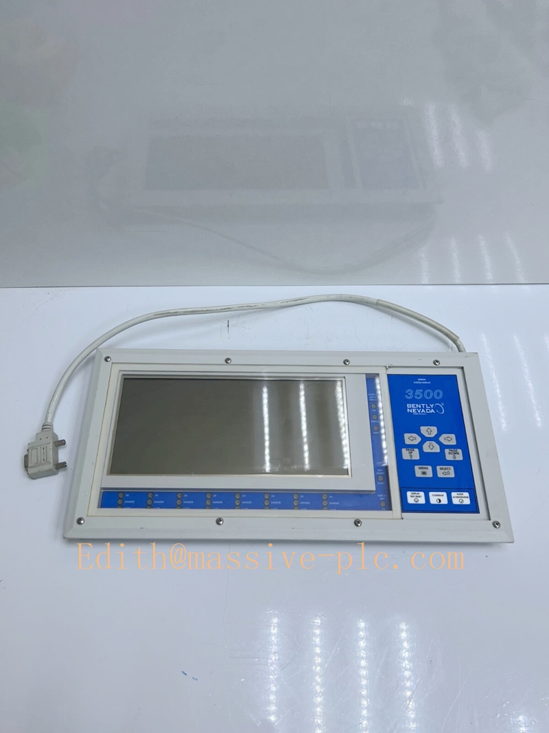
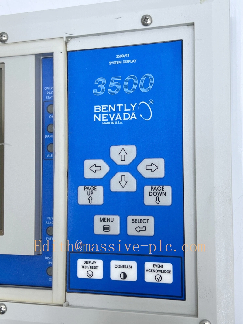
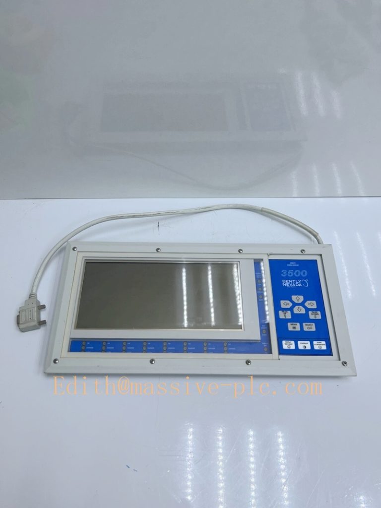
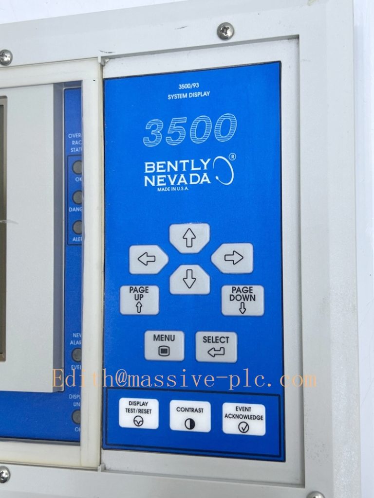
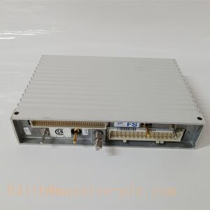
Bently Nevada 3500/93 (135785‑01) System Display Unit
Model Introduction
Model: 3500/93 System Display Unit Part Number: 135785‑01 Device Type: External local‑operator LCD display panel for 3500 machinery protection rack Manufacturer: Bently Nevada (Baker Hughes) System Compatibility: Must work with rack‑insert DIM module 135799‑01 (Display Interface Module) installed in slot‑15 of full‑size 3500 rack. Communicates via RS‑485 differential bus. Not compatible with 3500 mini‑rack. One rack supports maximum two pieces of 135785‑01 display units. Application Scenarios: TSI turbine supervisory instrumentation, thermal‑power steam turbines, oil‑gas centrifugal compressors. Provides on‑site local human‑machine interface, shows real‑time vibration, displacement, speed, temperature, channel alarm, danger status and system event list. Complies with API‑670 standard. Country of Origin: United States Lifecycle Status: Obsolete legacy hardware, OEM manufacturing discontinued; only aftermarket spare‑part support available. Successor revision: 135785‑02 (backlight‑enhanced version).
Note: System composition clarification:
- 135799‑01: DIM, rack‑slot‑15 front‑insert communication interface board (inside rack)
- 135785‑01: External System Display Unit, LCD screen with keypad (operator panel outside rack) These two parts must be used together; cannot work individually. 135785‑01 is non‑backlight reflective LCD variant.
350093 135785-01
Technical Introduction
Core Functions
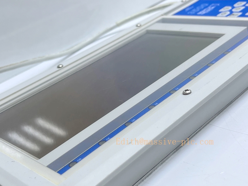
‑ Real‑time display of all rack channel measured values: vibration, displacement, speed, temperature, keyphasor data. ‑ Visual LED alarm indication: Unit OK, Rack OK, Rack Alert, Rack Danger; per‑channel OK / Alert / Danger LED indicators. ‑ Access system event log and alarm event log locally via front keypad. ‑ Four mounting options: face‑mount on rack front, 19‑inch EIA rack‑mount, panel‑mount, independent wall‑mount. ‑ Communication distance: up to 100 ft powered by DIM; with external 24 VDC power supply, extend up to 4000 ft over RS‑485 cable. ‑ Receive data from DIM(135799‑01) via proprietary RS‑485 protocol; not a Modbus gateway, no direct DCS output.
Key Technical Specifications
| Item | Parameter |
|---|---|
| Display Type | Reflective FSTN LCD, 640 × 200 dots, non‑backlighted |
| Keypad | Membrane function keypad for menu navigation |
| Communication Interface | RS‑485 (proprietary Bently protocol) |
| Typical Update Rate | 1 second per channel |
| Power Supply | Powered from DIM module; long‑distance installation requires external 24 VDC power |
| Operating Temperature | ‑30 ℃ ~ +65 ℃ |
| Storage Temperature | ‑40 ℃ ~ +85 ℃ |
| Humidity | 5 %‑95 % non‑condensing |
| Dimension | 412.8 mm × 203.2 mm × 31.2 mm |
| Weight | 2.1 kg |
| Compliance | API‑670, Class 1 Div 2 certification for hazardous area |
Mechanical Feature
Stand‑alone panel‑type display unit, not inserted into 3500 rack slots. Connect to rack‑internal DIM(135799‑01) by shielded RS‑485 twisted‑pair cable. Multiple mounting styles available for cabinet‑door or separate console installation. No hot‑swap for display itself; power‑off before wiring modification.
Adaptive Quality Assurance & Test Protocol
3.1 Factory Adaptive QA Procedure
- Visual inspection: Check LCD panel, membrane keypad, LED indicator integrity, housing mechanical condition.
- RS‑485 communication interoperability test: Pair with genuine 135799‑01 DIM module; verify stable data receiving under simulated long‑distance cable condition.
- Full‑data synchronization test: Verify real‑time value, alert/danger LED trigger, system‑event‑list synchronization.
- Keypad functional test: Navigate menu, browse channels, view event records, confirm key‑response without dead‑key.
- Alarm simulation test: Simulate channel alert / danger / trip condition; validate LED status and screen alarm prompt.
- EMC noise immunity test for RS‑485 communication port.
- Serial‑number traceability, part‑number marking verification, full functional‑test report archived.
3.2 On‑site Acceptance Test Protocol
- Visual inspection: Check display housing, LCD screen, keypad and LED indicators without physical damage.
- System‑wiring test: Connect RS‑485 cable between 135785‑01 display unit and 135799‑01 DIM front‑module edge connector; apply correct bus termination resistor.
- Power‑on test: Confirm unit‑OK LED lights up normally; screen loads rack channel information.
- Data‑consistency cross‑check: Compare display readings against 3500 Rack Configuration Software online values.
- Alarm‑trigger test: Force channel alarm condition; verify corresponding Alert / Danger LED and screen alarm message activate.
- Event‑list verification: Browse system‑event log and alarm‑event log via front keypad.
- Communication‑break simulation: Disconnect and reconnect RS‑485 cable; confirm communication‑loss prompt, auto‑recover after cable restore.
- Test‑record filing: Log part‑number, hardware revision, test‑result snapshot for site QA archive.
350093 135785-01
Field Engineer Technical Notes
Installation Guidance
‑ Mandatory matching rule: 135785‑01 display unit must pair with DIM module 135799‑01 installed in slot‑15 of full‑size 3500 rack. Cannot work without DIM board. ‑ RS‑485 wiring: Use shielded twisted‑pair cable; set bus terminal resistor; single‑end shield grounding, avoid multi‑point ground‑loop. ‑ For cable length over 100 ft, must add external 24 VDC power supply for display unit. ‑ Important note: This is only local operator display; it cannot output Modbus signal to DCS/PLC. For DCS communication, additional gateway module (3500/91 /91M /92) is required.
Field note: 135785‑01 is non‑backlight LCD; poor visibility in low‑light cabinet environment. For dim‑light application, select improved revision 135785‑02 with backlight. OEM original production stopped, spare‑parts come from aftermarket inventory.
Commissioning Tips
‑ After DIM module installation, download complete rack configuration; DIM automatically transmits rack dataset to connected 135785‑01 display. ‑ Verify RS‑485 cable polarity and termination resistor setting, wrong polarity causes no‑communication. ‑ Cross‑validate: channel value, alarm status, event list must be consistent between display unit and configuration software. ‑ Multiple‑display application: maximum two 3500/93 display units can be connected to one DIM module.
Troubleshooting Common Issues
- Display power‑on but no rack data: Check RS‑485 cable polarity, termination resistor, confirm DIM module sits in slot‑15 and no hardware fault.
- LED indicator abnormal: Check rack system event‑log for DIM‑communication fault codes.
- Partial channel missing on display: Re‑download rack configuration; confirm all monitor modules are healthy.
- Intermittent communication dropout: Check cable shielding and grounding; eliminate ground‑loop interference.
- Dim screen visibility: 135785‑01 has no backlight; upgrade to 135785‑02 for low‑light cabinet environment.
Diagnostic reference: Read rack system event‑log inside 3500 Rack Configuration Software for DIM communication fault information.
Maintenance & Spare‑part Recommendation
‑ No user‑serviceable components inside display unit; replace complete 135785‑01 unit upon hardware failure. ‑ Spare‑part suggestion: Maintain matched full set: 135799‑01(DIM) + 135785‑01(display) for legacy racks. For new spare‑procurement, consider 135785‑02 backlight‑version or migrate to PC‑software monitoring solution. ‑ Preventive inspection during shutdown: Check RS‑485 connector tightness, cable aging and shielding integrity, keypad aging condition.
3500/93 System Hardware Matching Table
| Part Number | Hardware Description | Installation Location | Mating Hardware |
|---|---|---|---|
| 135799‑01 | DIM Display Interface Module | Rack slot‑15 (inside full‑size rack) | 135785‑01 /135785‑02 display unit |
| 135785‑01 | System Display Unit (non‑backlight) | External operator panel | 135799‑01 DIM module |
| 135785‑02 | System Display Unit (with backlight) | External operator panel | 135799‑01 DIM module |

 Start Chat




