
Description
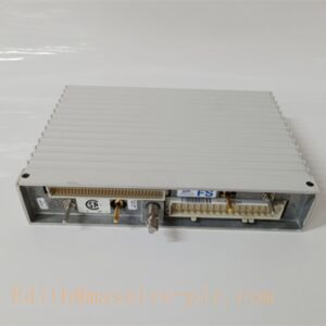
Bently Nevada 3500/91 (161216‑01) Rear I/O Card
Model Introduction
Model: 3500/91 Part Number: 161216‑01 Device Type: EGD Communication Gateway Rear I/O Module (back‑plane rear card) Manufacturer: Bently Nevada (Baker Hughes) System Compatibility: 3500 Series Machinery Protection System, paired with front‑side 3500/91 main gateway module, cannot operate independently. Application Scenarios: Turbine supervisory instrumentation (TSI), power generation, oil‑gas compressors, rotating machinery condition monitoring. It provides rear‑side wiring termination for Ethernet and auxiliary signal interfaces, bridging the 3500 rack backplane to external DCS, SCADA, PLC and network hosts. Country of Origin: United States Lifecycle Status: Legacy mature product, spare‑part support available, not end‑of‑life.
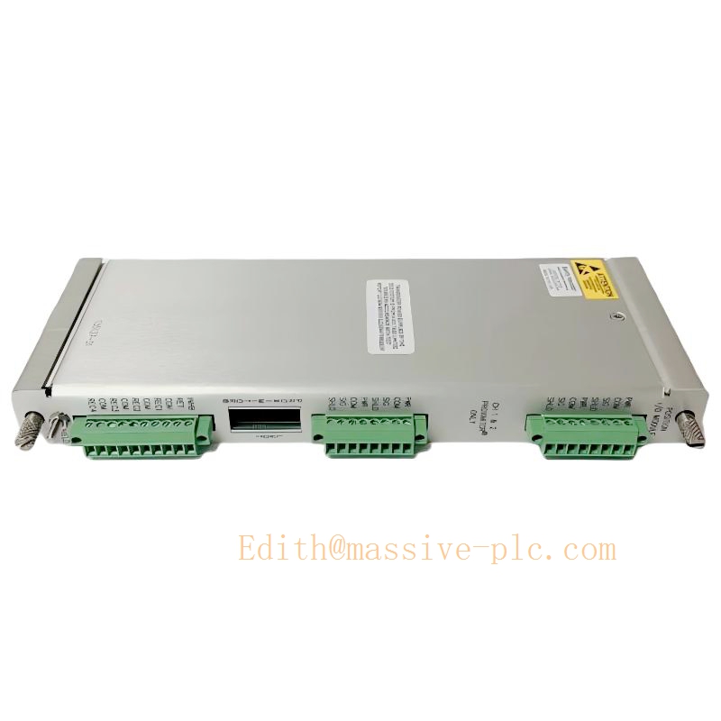
161216-01
Technical Introduction
Core Functions
- Provides rear‑panel physical termination for 10/100BASE‑TX Ethernet EGD gateway communication; supports Modbus‑TCP, Modbus RTU and native Bently Nevada protocol data transmissionBaker Hugh….
- Routes rack backplane bus data to external industrial networks; transmits real‑time vibration, position, speed, alarm status and system event logs.
- Offers auxiliary discrete signal terminals for system reset, trip multiply and rack alarm inhibit remote activation.
- Isolation protection for communication ports, suppresses industrial‑site surge and ground‑loop interference.
Key Technical Specifications
| Item | Parameter |
|---|---|
| Ethernet Interface | 10BASE‑T / 100BASE‑TX, auto‑negotiation |
| Bus Interface | 3500 rack proprietary backplane bus |
| Terminals | Euro‑style plug‑in screw terminals for auxiliary I/O; RJ45 Ethernet port |
| Power Supply | Supplied via 3500 rack backplane (24 VDC system power)CSDN博… |
| Operating Temperature | ‑30 ℃ ~ +65 ℃ |
| Storage Temperature | ‑40 ℃ ~ +85 ℃ |
| Humidity | 5 %‑95 % non‑condensing |
| Dimension | 241.3 mm × 24.4 mm × 99.1 mm |
| Weight | 0.39 kg |
| Compliance | API 670 compliant when full system properly configured; industrial EMC for heavy‑duty plant environment |
Mechanical Feature
This is a rear‑mount I/O card installed on the back side of the 3500 rack backplane, mated one‑to‑one with front‑inserted 3500/91 main module. Field wiring connects entirely to this rear card; front main module handles computation and protocol processing. Hot‑swap compatible under rack powered‑on condition (follow official maintenance procedure).
Adaptive Quality Assurance & Test Protocol
3.1 Factory Adaptive QA Procedure
- Backplane continuity test: Verify pin‑to‑pin connectivity between rear‑card connector and front‑module mating interface, check open‑circuit / short‑circuit fault.
- Ethernet physical‑layer adaptive test: Auto‑negotiation verification for 10 Mbps /100 Mbps full‑duplex & half‑duplex mode; link‑up / link‑down stress cycle test.
- Protocol adaptive validation: EGD packet transmission, Modbus‑TCP register read‑write, event‑message forwarding test against 3500 rack simulation environment.
- Auxiliary discrete‑channel test: Trigger remote reset, trip‑multiply, alarm‑inhibit signals to confirm correct logic response.
- Environmental screening: Temperature cycling test; surge‑immunity test for communication ports.
- Built‑in self‑diagnostic execution: Module internal self‑test; event‑log generation; fault‑flag reporting validation.
- Final compliance check: Serial‑part‑number traceability, label verification, functional‑test report archived.
3.2 On‑site Acceptance Test Protocol
- Visual inspection: Check physical condition, connector pin integrity, no mechanical damage.
- Rack insertion test: Install rear I/O card and matched front main module; power‑on, read module status via 3500 Rack Configuration Software, confirm no hardware mismatch alarms.
- Communication link test: Connect Ethernet cable, verify link LED status; establish Modbus‑TCP connection from host, read real‑time measurement and alarm registers.
- Auxiliary input function test: Inject dry‑contact signals to rear‑card auxiliary terminals, confirm corresponding system actions are triggered.
- Self‑test run: Launch module self‑test from configuration software; confirm zero critical faults in system event list.
- Fail‑over simulation: Simulate network cable disconnection and reconnection; verify module auto‑recovery without rack system crash.
- Test record filing: Log part number, firmware version, test‑result snapshot for site QA archive.
Field Engineer Technical Notes
Installation Guidance
- The 161216‑01 rear I/O card must be paired with matching 3500/91 front main module; cross‑part‑number mixing will trigger I/O‑mismatch fault and communication failure.
- Install on rack back‑side, align backplane connector firmly; tighten retaining screws to avoid loose‑contact intermittent faults.
- Ethernet cable: Use industrial‑grade shielded CAT5e/CAT6 cable; shield single‑end grounding following plant drawing, avoid multiple ground loops.
- Auxiliary signal wiring: Use dry‑contact isolated relay outputs for remote‑control signals; do not feed external voltage directly into rear‑card discrete terminals.
Commissioning Tips
- Complete rack configuration download after hardware installation; confirm gateway module is activated in slot configuration.
- Assign static IP address for 3500/91 via Rack Configuration Software; avoid IP conflict within plant LAN.
- Map Modbus register table according to project document; verify vibration, position, alert/danger alarm bits read correctly at DCS side.
Troubleshooting Common Issues
- Module Mismatch Alarm: Rear‑card and front‑module part‑revision mismatch; confirm correct matching spare‑part number.
- Ethernet link down: Inspect RJ45 connector, cable continuity, switch port status; check IP subnet matching.
- Data loss / intermittent communication: Check grounding & shielding; eliminate ground‑loop interference; verify network switch anti‑storm‑control setting.
- Auxiliary remote signal no response: Check terminal wiring continuity, dry‑contact integrity; confirm function is enabled in rack configuration.
Diagnostic reference: Read system event list inside 3500 software to locate hardware or configuration faults.
Maintenance & Spare‑part Recommendation
- No on‑board user‑repairable components; upon hardware failure replace complete rear‑card assembly.
- Recommended spare‑part stock: keep matched front‑main‑module plus rear‑I/O‑card set.
- Preventive check during turnaround: Inspect terminal screw tightness, connector oxidation, cable aging.
Related 3500 Series Rear I/O Card Family
| Front Module Model | Rear I/O Part No. | Module Description |
|---|---|---|
| 3500/91 | 161216‑01 | EGD Communication Gateway Rear Card (this item) |
| 3500/91M | 190783‑01 | Enhanced EGD Gateway Rear I/O |
| 3500/42M | 128229‑01 | Proximitor / Seismic Monitor Rear CardCSDN博… |
| 3500/40M | 132306‑01 | 4‑Channel Proximitor Monitor Rear Card |
| 3500/32M | 141712‑01 | 4‑Channel DPDT Relay Rear I/O |
| 3500/33 | 162292‑01 | 16‑Channel SPDT Relay Rear Card |
| 3500/25 | 141535‑01 | Enhanced Keyphasor Rear I/O |
| 3500/53 | 148452‑01 | Overspeed Monitor Rear Card |

 Start Chat




