
Description
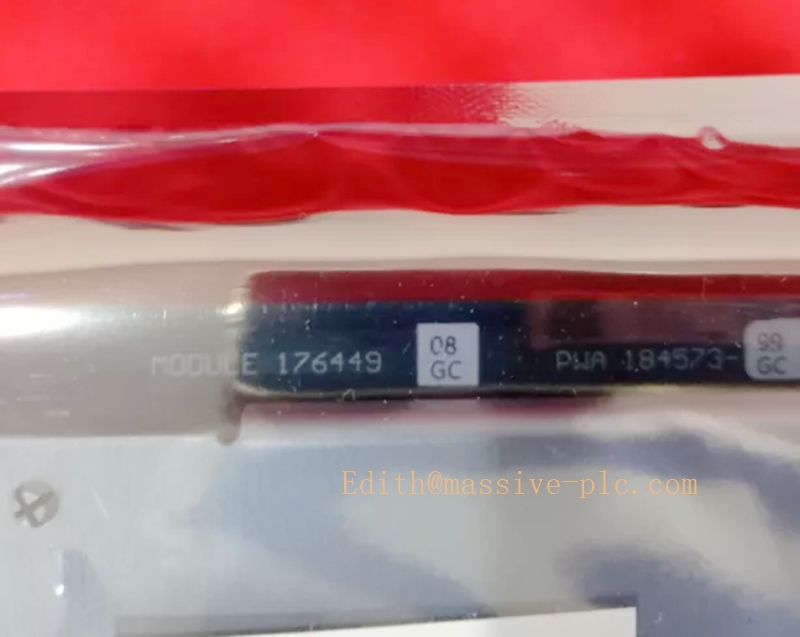
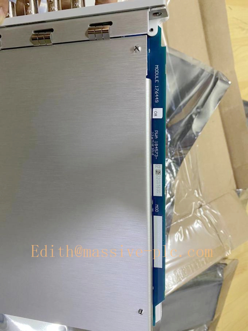
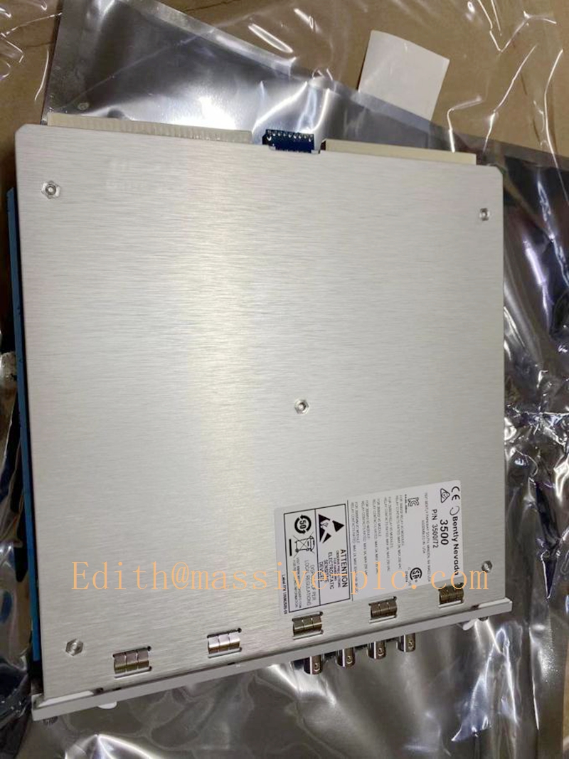
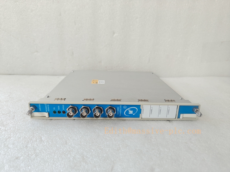
Bently Nevada 3500/44M (176449‑03) Aeroderivative Gas Turbine Vibration Monitor Mainboard
350040-01-00 176449-01
Product Introduction
176449‑03 is the front‑plug main processing board for the Bently Nevada 3500/44M Aeroderivative Gas Turbine Vibration Monitor, USA‑origin critical TSI protection module. It is the hardware‑equivalent successor revision of 140734‑03, implementing high‑speed tracking‑filter algorithms optimized for aeroderivative gas turbines. It acquires vibration signals from accelerometers and Velomitor velocity sensors via matched rear Aero‑GT I/O assembly (126599‑01). It supports 1X amplitude‑phase tracking, signal integration and band‑pass filtered vibration measurement referenced to Keyphasor speed input. Compliant with API‑670 and SIL‑2 capable, it delivers machinery protection and condition monitoring functions. This mainboard cannot operate standalone and must mate with dedicated 3500/44M I/O assembly, incompatible with 3500/42M I/O hardwareReliabilit…. Widely deployed in power generation, oil‑gas industries for LM‑series, RR and other aeroderivative gas turbine packages.
Typical Applications ‑ Vibration protection and condition monitoring for aeroderivative gas turbine engines ‑ 1X synchronous vibration tracking during unit start‑up, shutdown and variable‑load transient operating conditions ‑ Casing acceleration / velocity vibration measurement for high‑speed gas turbine equipment ‑ Band‑pass filtered vibration monitoring for bearing fault, blade pass and combustion‑related anomaly diagnosis ‑ Accept independent Keyphasor speed & phase reference signals from 3500/50 module ‑ Transmit measured vibration data to DCS, PLC and host monitoring software over 3500 rack backplane bus
Technical Specifications
| Item | Specification |
|---|---|
| Part Number | 3500/44M, 176449‑03 (Monitor Mainboard) |
| Channel Quantity | 4 vibration input channels, operated as two independent channel‑pairs |
| Supported Transducers | Accelerometers, Velomitor velocity sensors |
| Core Measurement Functions | Acceleration, velocity, integrated velocity, 1X tracking vibration, band‑pass filtered vibration |
| Keyphasor Reference | Supports up to 2 independent Keyphasor inputs for separate channel‑pair tracking filters |
| ADC Resolution | 24‑bit high‑resolution sampling |
| Frequency Response | 4 Hz ~ 30 000 Hz (-3 dB, unintegrated acceleration) |
| Measurement Accuracy | ±1 % full‑scale |
| Power Supply | Powered by 3500 rack backplane, 24 VDC nominal |
| Max Power Consumption | 7.7 W |
| Operating Temperature | ‑40 °C ~ +85 °C |
| Communication | 3500 internal system backplane bus; Modbus RTU over RS‑485 |
| Certifications | SIL‑2 capable, API‑670 compliant, CE / RoHS |
| Approximate Weight | 0.38 kg |
| Installation Form | Hot‑swap plug‑in front‑mount module for 3500‑series rack slots |
Important Remark: 176449‑03 is main processing board only. Must pair with dedicated Aero‑GT I/O assembly 126599‑01. Physical slot compatibility with 3500/42M I/O assembly does not guarantee functional compatibility, cross‑model pairing will cause measurement failureReliabilit….
Key Features
- Aeroderivative gas turbine optimized algorithm: each channel‑pair owns independent tracking filter, adapts to wide‑range speed variation during turbine transient processes.
- Multi‑mode signal processing: onboard hardware signal integration, 1X amplitude‑phase tracking, configurable band‑pass filter for targeted frequency‑band monitoring.
- Dual‑level alarm mechanism: user‑programmable Alert and Danger setpoints; configurable alarm delay 0‑60 s; composite alarm logic for relay‑output protection interlock.
- Front‑panel coaxial buffered recorder outputs for portable instrument signal acquisition and on‑site troubleshooting.
- Hot‑swap capability: module replacement without rack power interruption.
- Comprehensive onboard diagnostics: sensor open‑circuit / short‑circuit detection, Keyphasor signal abnormality diagnosis, internal hardware self‑test, time‑stamped event logging stored in non‑volatile memory.
- Configuration parameters saved inside module; programmed via 3500 Rack Configuration Software.
- High‑EMI‑immunity industrial hardware for harsh gas‑turbine package environments.
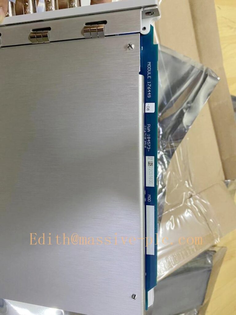
350040-01-00 176449-01
Adaptive Quality Assurance and Test Protocol (AQAT)
The Adaptive Quality Assurance and Test Protocol defines factory and site acceptance‑test workflows for 3500/44M 176449‑03 mainboard, validating tracking‑filter performance, signal‑path integrity, alarm‑logic accuracy and long‑term operational stability.
4.1 Factory‑Side Adaptive QA Test
‑ Power‑on self‑diagnostic cycle: verify hardware register status, backplane communication, watchdog and Keyphasor reference receiving function. ‑ Channel‑by‑channel signal injection: input simulated acceleration and velocity vibration signals; validate gain, offset, linearity and frequency‑response versus datasheet tolerances. ‑ Tracking‑filter performance test: apply variable‑speed Keyphasor reference together with vibration stimulus; verify 1X amplitude‑phase tracking output accuracy. ‑ Alarm‑threshold verification: step input signal across Alert / Danger setpoints; confirm alarm‑trigger accuracy, relay‑action response and timestamped‑event logging. ‑ Transducer‑fault simulation: simulate open‑circuit / short‑circuit conditions to validate sensor‑fault alarm reporting. ‑ Powered temperature‑cycling burn‑in screening to eliminate early‑life component‑failure risk. ‑ Generate formal factory test report and configuration backup prior to shipment.
4.2 Site‑Side Adaptive QA Procedure
‑ Installation Qualification (IQ): verify rack‑slot seating, backplane contact integrity, correct mechanical‑electrical mating with 126599‑01 Aero‑GT I/O assembly, grounding scheme and cable‑routing compliance. ‑ Operational Qualification (OQ): perform on‑site signal‑injection testing; cross‑validate measurement readings, 1X‑tracking output, alarm‑trigger performance and host‑system data consistency. ‑ Performance Qualification (PQ): long‑run observation under real gas‑turbine operating conditions; cross‑compare module readings with portable vibration‑analyser measurements. ‑ Adaptive retest: execute full‑channel verification after mainboard replacement, sensor swap or configuration modification; archive all test records for audit traceability.
All test documentation shall be retained for asset‑management and audit purposes.
Field Engineer Technical Instructions
5.1 Installation Guidance
‑ Insert 3500/44M (176449‑03) mainboard into vacant slot of 3500‑series rack. Hot‑swap operation is permitted while rack remains powered. Fasten module latches to guarantee reliable backplane contact. ‑ Install dedicated rear Aero‑GT I/O assembly 126599‑01. Do NOT adopt 3500/42M‑series I/O assemblies. ‑ Route accelerometer and Velomitor transducer cables away from high‑voltage power cables; comply with maximum transducer‑cable‑length limits. ‑ Follow plant‑site grounding specification: separate analog‑signal grounding from heavy‑power grounding to minimize noise‑coupling effects. ‑ Confirm valid Keyphasor signal source supplied from 3500/50 module for tracking‑filter function.
5.2 Commissioning
‑ Complete mechanical assembly of 3500/44M mainboard plus 126599‑01 I/O assembly and field‑sensor wiring. ‑ Launch 3500 Rack Configuration Software, select module type 3500/44M, assign channel‑pair processing modes, configure transducer sensitivity, filter parameters, Alert and Danger alarm thresholds, assign Keyphasor reference source for each channel‑pair. ‑ Download configuration parameters to module memory and perform module reset to activate parameters. ‑ Verify Keyphasor speed and phase signal quality before enabling 1X tracking‑filter functions. ‑ Validate raw vibration readings; force‑test each channel to confirm relay‑output action and HMI / DCS‑indication consistency.
5.3 Typical Field Troubleshooting
‑ Sensor‑fault alarm: Inspect field‑cable open‑circuit / short‑circuit faults, terminal screw tightness and transducer physical damage. ‑ Abnormal 1X‑tracking output: Check Keyphasor trigger gap and signal amplitude; review filter configuration parameters; inspect grounding and EMI interference sources. ‑ Measurement drift: Verify grounding integrity, noise interference and transducer‑cable aging conditions. ‑ Communication loss: Inspect rack‑backplane health, slot‑contact condition and system‑controller operating status.
Warning: Bypass protection alarms only for short‑duration maintenance work. Restore full‑protection functions before aeroderivative gas turbine returns to normal‑operation status.
5.4 Maintenance
‑ Observe front‑panel LED‑status indicators during routine site rounds. ‑ Do not open module housing; there are no user‑serviceable internal components. ‑ Preserve complete configuration‑backup file for rapid hardware replacement upon mainboard failure.
Related / Similar Series Models
| Model | Brief Description |
|---|---|
| 3500/44M‑176449‑03 | 4‑ch Aeroderivative Gas Turbine Vibration Monitor Mainboard, updated revision |
| 3500/44M‑140734‑03 | Former‑revision 3500/44M main processing board |
| 126599‑01 | Dedicated Aero‑GT rear I/O assembly for 3500/44M |
| 3500/42M‑140734‑02 | General‑purpose Proximitor / Seismic Monitor (not for Aero‑GT tracking filter) |
| 3500/45M | Auxiliary position‑monitor module |
| 3500/46M | Hydro‑turbine dedicated monitor module |
| 3500/50 | Keyphasor module for shaft phase reference and rotational‑speed acquisition |



 Start Chat




