
Description
Bently‑Nevada 3500/15 129489‑01 High‑Voltage DC Power Input Module (PIM)
Product Description
The 129489‑01 is a rear‑mounted High‑Voltage DC Power Input Module (PIM) for the Bently‑Nevada 3500/15 power‑supply subsystem within the 3500 machinery‑protection rack. It mechanically attaches to the rear connector of the front‑side high‑voltage DC main power board 129486‑01. This PIM serves as the physical field DC power interface, provides fuse‑based input protection, and routes filtered high‑voltage DC power to the main power‑supply board for conversion into multi‑rail regulated DC for the entire rack backplane. It is a half‑height legacy spare component and cannot operate independently without the corresponding front‑side main power‑supply module本特利(B…. OEM original production has been discontinued; it is only available as aftermarket replacement spare part for existing 3500 TSI installations.
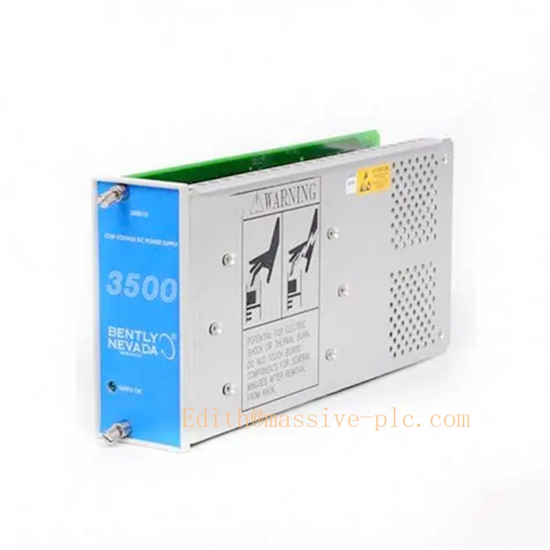
129489‑01
Technical Specifications
| Item | Specification |
|---|---|
| Part Number | 129489‑01 (High‑Voltage DC Power Input Module, PIM) |
| Matching Front Main Power Board | 129486‑01 |
| DC Input Voltage Range | 88‑140 VDC nominal high‑voltage DC field power |
| Max Full‑Rack Input Current | 4.5 A DC |
| Internal Protection | Integrated input fuse (PN 01720025) for over‑current and surge protection |
| Form Factor | Half‑height rear‑mount daughter‑board, installed directly behind main power‑supply board |
| Operating Temperature | ‑30 °C ~ +65 °C (‑22 °F ~ +150 °F) |
| Storage Temperature | ‑40 °C ~ +85 °C (‑40 °F ~ +185 °F) |
| Relative Humidity | 5‑95 % RH, non‑condensing |
| Dimension | 120.7 mm × 25.4 mm × 114.3 mm (4.75 in × 1.0 in × 4.5 in) |
| Weight | 0.34 kg (0.75 lbs) |
| Product Status | Discontinued OEM production, aftermarket spare‑part only |
3500/15 High‑Voltage DC power assembly pairing: Main board 129486‑01 + rear PIM board 129489‑01 = complete high‑voltage DC power‑supply unit本特利(B….
Key Features & Benefits
- Dedicated high‑voltage DC field interface: Designed for plant‑supplied 88‑140 VDC battery‑derived power source, delivering filtered DC input to the 3500/15 main power‑supply conversion board.
- Built‑in fuse protection: Factory‑fitted input fuse defends the entire rack from surge, over‑current and short‑circuit faults, improving system survivability under harsh site power disturbances.
- Rack‑native plug‑and‑play mechanical design: Exact mechanical fit for legacy 3500 rack rear‑side power slot; no cabinet modification required during spare‑part replacement.
- Supports 1+1 hot‑redundant power architecture: Two complete high‑voltage DC power assemblies can run in parallel hot‑backup mode. Mixed‑type redundancy (DC‑AC combination) within a single rack is also permitted.
- Wide industrial environmental tolerance: Operates reliably across broad temperature and humidity ranges, suitable for standard industrial control‑cabinet installation.
- Full backward compatibility: Matches all legacy 3500 monitor modules, RIM hardware and system firmware revisions.
Application Fields
- Machinery‑protection racks for steam turbines, gas turbines and centrifugal compressors in power‑generation combined‑cycle plants with high‑voltage DC station‑battery infrastructure.
- Petrochemical refineries and natural‑gas processing facilities for critical rotating‑equipment TSI vibration‑monitoring cabinets fed from 88‑140 VDC field power.
- Heavy‑industry rotating‑machinery condition‑monitoring systems relying on high‑voltage DC backup power supplies.
- Spare‑part replacement and hardware retrofit for existing legacy 3500 installations configured for high‑voltage DC power input.
Related Recommended Products
- 129486‑01: Front‑side high‑voltage DC main power‑supply board (must pair with 129489‑01 for complete power‑supply assembly)
- 01720025: Replacement spare fuse for high‑voltage‑DC and AC‑type PIM modules
- 133292‑01 +133300‑01: Low‑voltage DC power‑supply set (24 VDC nominal input)
- 3500/20 (125744‑01): TMR Rack Interface Module for rack‑level communication, event logging and diagnostics
- 3500/25: Keyphasor timing‑reference module for shaft‑speed and phase‑angle measurement
- 3500/40M: Proximity and vibration monitor module for shaft‑vibration and thrust‑position protection
Installation and Maintenance
Installation
- Assemble the power‑supply unit first: firmly mount 129489‑01 PIM onto the rear‑side connector of 129486‑01 main power‑supply board before inserting into rack.
- Insert the assembled power‑supply unit into the designated half‑height power slot on the far‑left side of the 3500 rack.
- Wire site 88‑140 VDC power source to the screw‑terminal block of 129489‑01; strictly follow grounding and wiring requirements specified within Bently‑Nevada official installation manual.
- For redundant configuration, install a second fully assembled power‑supply unit into the adjacent left‑side power slot. Mixed AC‑DC redundant power combination is allowed.
- After power‑on, verify front‑panel “SUPPLY‑OK” LED status; confirm power‑supply health status via 3500 rack configuration software.
Important Note: 129489‑01 cannot function as standalone hardware. Never apply field DC power to the PIM without proper mechanical mating to matching front‑side main power‑supply board.
Maintenance
- Conduct periodic visual inspection: check screw terminals and housing for signs of over‑heating, dust accumulation and loose wiring connections.
- If input fuse blows, identify and eliminate root‑cause field‑power fault before fitting replacement fuse PN 01720025. Never install over‑rated replacement fuses.
- Hot‑swap maintenance is available for redundant‑power racks: replace defective PIM‑and‑power‑supply assembly without shutting down the whole machinery‑protection rack, on condition that the second healthy power‑supply remains in normal operation.
- Avoid mechanical shock and conductive contamination to rear‑side PIM printed‑circuit assembly during module handling and replacement.
- Refer to official 3500‑series power‑supply operation‑and‑maintenance manual (document 129767‑01) for detailed fault‑isolation and troubleshooting procedures.


 Start Chat




