
Description
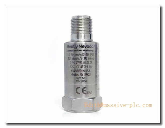
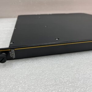
Bently Nevada 330425‑02‑05 330425 Accelerometer Acceleration Transducer (Multi‑Hazardous‑Area Approvals Variant)
Product Overview
The 330425‑02‑05 is a piezoelectric loop‑powered accelerometer from Bently Nevada 330425 series, designed for casing‑mounted acceleration‑based machinery condition monitoringBaker Hugh…. It converts casing vibration into proportional analog acceleration signal for turbomachinery monitoring systems. Unlike eddy‑current proximity probes measuring shaft‑relative displacement, this accelerometer measures absolute casing vibration, widely used for gear‑mesh analysis, bearing‑housing vibration monitoring on turbines, compressors, fans and pumps. It complies with API‑670 requirements for accelerometer transducers.
Critical Compatibility Warning
- Requires compatible Bently Nevada monitor channels supporting loop‑powered accelerometer input (3500/3300 series monitor modules).
- Mating connector: part number 00531080 3‑pin female connector at sensor top endBaker Hugh….
- Compatible signal cables: 16925‑XX (non‑armored), 16710‑XX (armored) 3‑conductor shielded cables, max 30 m total length.
- Suffix‑05 means multi‑agency hazardous‑area certifications (ATEX, IECEx, CSA). Always cross‑check physical label for zone classification before field installation in explosive atmosphere.
Part Number Decoding
- 330425:Base accelerometer model, 25 mV/g sensitivity, 75 g peak measurement range
- ‑02:Mounting stud thread: M8×1 integral male studBaker Hugh…
- ‑05:Multi‑approval option: ATEX / IECEx / CSA hazardous‑area certifications included
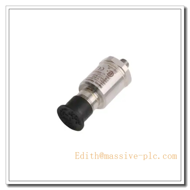
330425-02-05
Key Specifications
| Parameter | Value |
|---|---|
| Part Number | 330425‑02‑05 |
| Series | 330425 Loop‑Powered Accelerometer |
| Sensitivity | 25 mV/g (2.55 mV/(m/s²)), ±5 % @100 Hz |
| Measurement Range | 75 g peak (735 m/s² peak) |
| Frequency Response | 10 Hz‑15 kHz ±3 dB; 30 Hz‑10 kHz ±10 % |
| Mounted Resonant Frequency | ≥30 kHz |
| Transverse Sensitivity | ≤5 % of axial sensitivity |
| Power Supply | ‑24 Vdc ±4 Vdc loop power, 2 mA bias current typical |
| Output Bias Voltage | ‑8.5 Vdc ±0.5 Vdc |
| Output Impedance | 50 Ω typical |
| Broadband Noise Floor | 0.008 g rms typical (10‑15 kHz) |
| Mounting Thread | M8×1 integral stud |
| Operating Temperature Range | ‑50 °C ~ +120 °C |
| Housing Material | 316 stainless‑steel |
| Certifications | API‑670 compliant; ATEX, IECEx, CSA hazardous‑area approvals (‑05 suffix) |
| Country of Origin | USA |
| Weight | ≈0.11 kg |
Main Features
- Loop‑powered piezoelectric accelerometer: Powered from monitor module, no local external power supply required.
- 25 mV/g sensitivity, 75 g peak full‑scale: Optimized for high‑vibration casing monitoring, gear‑mesh and high‑frequency fault detection.
- M8×1 integral mounting stud: Standard mechanical interface for industrial machinery casing installation.
- Multi‑hazardous‑area certifications (‑05): ATEX / IECEx / CSA approvals, suitable for petrochemical, refinery and oil‑gas classified zone sites.
- Stainless‑steel rugged housing: Resists oil mist, humidity and continuous machinery vibration.
- Wide frequency bandwidth: Captures low‑speed vibration up to high‑frequency gear‑mesh signatures.
- **API‑670 compliant performance for turbomachinery protection & condition‑based monitoring.
Typical Application Scenarios
- Absolute casing vibration monitoring for steam turbines, gas turbines, centrifugal compressors
- Gear‑box high‑frequency gear‑mesh fault detection on critical rotating equipment
- Bearing‑housing vibration measurement for large fans, blowers and process pumps
- Refinery, petrochemical and power‑plant projects requiring ATEX/IECEx hazardous‑area certified accelerometers
- New‑project deployment for Bently Nevada 3500 rack monitoring systems
- Overhaul spare‑part replacement for existing 330425 series accelerometer measurement loops
Related & Recommended Alternative Models
| Model | Description |
|---|---|
| 330425‑01‑05 | Accelerometer, 1/4‑28 UNF stud, multi‑hazardous‑area approvals |
| 330425‑02‑00 | M8×1 stud, no hazardous‑area agency approvals |
| 330400‑02‑05 | 50 g peak, 100 mV/g sensitivity accelerometer (higher sensitivity variant) |
| 00531080 | Mating 3‑pin connector for 330425 series accelerometerBaker Hugh… |
| 37439‑02 | M8×1 anti‑base‑strain mounting base accessory |
Compatible Components & Accessories
- Monitor hardware: Bently Nevada 3500 series accelerometer input modules, 3300 series monitors
- Signal cables: 16925‑XX non‑armored, 16710‑XX armored 3‑conductor shielded accelerometer cables
- Connector: 00531080 mating 3‑pin female connector
- Mechanical accessories: 37439‑02 mounting base, 43217 accelerometer mounting kit
- Installation consumables: Anti‑seize compound, high‑temperature thread sealant, cable clamps
Installation and Configuration Guide
Warning: Installation shall be performed by qualified instrument technicians. Refer to original Bently Nevada 330400/330425 operation manual as primary reference. Verify hazardous‑area certification before deployment in explosive classified zones.
- Mechanical Mounting Preparation
- Select rigid, thick casing location; avoid thin flexible sheet‑metal surfaces.
- For serial numbers without prefix “G”, install 37439‑02 mounting base first to minimize base‑strain influence.
- Apply anti‑seize compound to M8×1 threads; torque accelerometer stud to manufacturer‑specified mounting torque value. Do not over‑torque.
- Mount accelerometer with sensing axis aligned to target vibration measurement direction.
- Cable and Connector Assembly
- Use approved 16925‑XX /16710‑XX series 3‑conductor shielded accelerometer cable; do not use proximity‑probe coaxial extension cables.
- Assemble mating connector (00531080) onto sensor top, tighten properly. Provide cable strain‑relief near connector to eliminate pulling stress.
- Route accelerometer signal cables separately from high‑power AC, VFD wiring to reduce EMI noise interference.
- System Wiring & Power‑up
- Wire cable terminal‑lug end to corresponding accelerometer monitor channel terminals according to manual pin‑out definition.
- Power‑up monitoring rack; read bias voltage to confirm sensor loop integrity. Normal bias voltage approx‑8.5 Vdc.
- Perform vibration signal check with machine static and running condition to validate signal quality.
- Commissioning & Alarm Setup
- Configure monitor channel sensitivity parameter to 25 mV/g for this 330425 accelerometer.
- Set alarm and trip thresholds according to project machinery vibration specification.
- Confirm no hardware fault status on monitor channel.
- Maintenance & Troubleshooting
- During machinery turnaround, inspect accelerometer mounting tightness, connector condition and cable jacket integrity.
- Abnormal bias voltage, zero output or noisy signal may indicate loose connector, cable damage or faulty accelerometer.
- Do not attempt to repair internal piezoelectric element; replace complete sensor unit upon failure.
Supplementary Remark
330425‑02‑05 is a loop‑powered API‑670 compliant accelerometer with M8×1 mounting stud and multi‑hazardous‑area ATEX/IECEx/CSA certifications, delivering 25 mV/g sensitivity and 75 g peak acceleration measurement for casing absolute‑vibration monitoring. It is not an eddy‑current proximity probe, requires dedicated accelerometer monitor channels and matching 3‑conductor signal cables. Before commissioning, cross‑check thread size, sensitivity, hazardous‑area approval, monitor‑channel compatibility and cable‑type requirement against project BOM and mechanical drawings.

 Start Chat




