
Description
Bently Nevada 330101‑00‑16‑10‑11‑CN — 3300‑XL 8 mm Eddy‑Current Proximity Probe
Product Overview
The 330101‑00‑16‑10‑11‑CN is an 8 mm eddy‑current proximity probe from Bently Nevada 3300‑XL transducer family. It is the field‑sensing element of non‑contact proximity measurement loops, working in conjunction with matched proximitor sensor and extension cable. The probe detects the gap variation between probe tip and metallic rotating target, and transmits impedance variation signal back to proximitor for signal conditioning. This probe follows API 670 standard and is widely deployed for vibration, thrust‑position and Keyphasor measurement on turbomachinery.
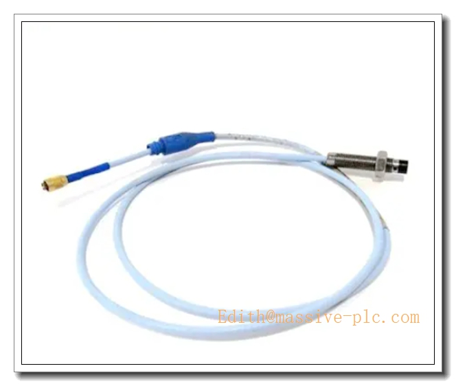
330101-00-16-10-11-CN
Specific Application Information
This probe is the field sensing head for 3300‑XL 5/8 mm proximity monitoring system:
- Radial shaft vibration measurement: Detect dynamic shaft radial movement for journal bearing health monitoring on turbines, compressors and critical rotating equipment.
- Axial thrust‑position monitoring: Measure static thrust‑shaft displacement to evaluate thrust‑bearing wear status.
- Keyphasor speed & phase reference: Installed as notch‑target probe to generate tachometer trigger pulses for rotor phase analysis and RPM calculation.
- Legacy system spare replacement: Drop‑in replacement for existing 3300‑XL 8 mm probe loops, CN suffix denotes commercial revision variant for global industrial spare‑part supply.
Key Specifications
| Parameter | Value |
|---|---|
| Part Number | 330101‑00‑16‑10‑11‑CN |
| Series | 3300‑XL 5/8 mm (8 mm) Proximity Probe |
| Probe Tip Diameter | 8 mm |
| Probe Body Thread | M10 ×1 male thread |
| Probe Body Length | 16 mm |
| Integral Pigtail Cable Length | 1.0 m |
| Connector Type | 11‑pin microdot connector |
| Scale Factor | 7.87 V/mm (200 mV/mil), calibrated for AISI‑4140 steel target |
| Linear Measurement Range | 2.0 mm (80 mils) |
| Frequency Response | 0 Hz ~ 10 kHz |
| Operating Temperature Range | ‑35 °C ~ +175 °C |
| Certifications | CE, ATEX, IECEx, CSA hazardous‑area approvals |
| Housing Material | Stainless steel |
| Calibration Target | Factory calibrated on AISI‑4140 steel |
| Country of Origin | USA |
| Weight | ≈0.12 kg |
Main Features
- Standard 8 mm 3300‑XL probe design: API‑670 compliant, compatible with full 3300‑XL 8 mm proximitor and extension‑cable product family.
- Compact short‑body form factor: 16 mm threaded body, suitable for limited‑space probe mounting holes and counter‑bore installations.
- High temperature resistance: Probe tip withstands up to +175 °C, adapts to high‑temperature machinery casing environments.
- Stainless‑steel robust construction: Resists vibration, shock, oil mist and moderate corrosive atmosphere in turbine/compressor casings.
- Integral 1 m pigtail with Microdot connector: Quick field mating with matched extension cable; reduces on‑site wiring work.
- ‑CN commercial revision: Optimized for global spare‑part distribution, mechanical & electrical performance fully equivalent to non‑CN original part.
- Intrinsic safety certification: Supports installation in ATEX / IECEx hazardous classified areas when used within complete certified 3300‑XL system.
- Consistent linear performance: Stable gap‑impedance characteristic, guarantees measurement accuracy within full 2.0 mm linear zone.
Typical Application Scenarios
- Steam & gas turbine machinery protection in power‑generation plants
- Centrifugal compressors for refinery, petrochemical and LNG facilities
- Critical large pumps, blowers, fans and fluid‑film‑bearing motors
- Off‑shore platform rotating‑machinery condition‑monitoring loops
- Pulp & paper, steel mill heavy rotating‑equipment safety monitoring
- Hazardous‑area classified sites requiring ATEX / IECEx intrinsic‑safety approval
- Retrofit & spare‑part replacement for existing 3300‑XL 8 mm proximity measurement channels
Related & Recommended Alternative Models
| Model | Description |
|---|---|
| 330101‑00‑12‑10‑11‑CN | 8 mm probe, 12 mm body length, 1 m pigtail, Microdot connector |
| 330101‑00‑20‑10‑11‑CN | 8 mm probe, 20 mm body length, 1 m pigtail, Microdot connector |
| 330103‑00‑xx‑xx‑xx‑xx | 3300‑XL 8 mm probe with longer pigtail cable variants |
| 330180‑51‑05 | 3300‑XL 8 mm proximitor, 5 m total‑system length, DIN‑rail mount |
| 330180‑71‑05 | 3300‑XL 8 mm proximitor, 7 m total‑system length, DIN‑rail mount |
| 330180‑91‑05 | 3300‑XL 8 mm proximitor, 9 m total‑system length, DIN‑rail mount |
Compatible Components & Accessories
- 3300‑XL 8 mm extension cables: 330130‑xx‑xx‑00 series, mate with Microdot connector of probe. Sum probe 1 m + extension cable = proximitor total‑system length rating.
- Matched 3300‑XL 8 mm proximitor: e.g. 330180‑51‑05 / 71‑05 /91‑05 DIN‑rail proximitor with corresponding total‑system length.
- Bently Nevada monitor modules: 3500/42M, 3300/12, 3300/15 monitor racks for gap‑voltage acquisition, alarm and trip configuration.
- Probe mounting hardware: M10×1 lock nut, compression fitting for probe mechanical installation onto machine casing.
- Calibration test fixture: Static gap calibration rig for pre‑commissioning performance verification.
- Torque wrench: For specified Microdot connector torque during field assembly.
Installation and Configuration Guide
Warning: Installation shall be completed by qualified instrumentation technicians. Always refer to original Bently Nevada 3300‑XL official manual as primary reference document.
- Mechanical Probe Mounting
- Install probe into machine casing threaded bore (M10×1 thread). Fit lock‑nut to lock probe position after gap adjustment.
- Ensure probe tip keeps perpendicular to metallic shaft target surface. Avoid tilt angle which degrades linear performance.
- Maintain proper clearance; no metal debris or mechanical collision between probe tip and rotating shaft during full shaft operating excursion.
- System Length Calculation
- Probe integral cable length =1 m. Select extension cable so that 1 m + extension cable length = exact rated total‑system length of paired proximitor. Any length mismatch will change scale factor and create measurement error.
- Torque Microdot coaxial connector to manufacturer specified torque value; do not over‑tighten. Never connect / disconnect coaxial connectors when proximitor power is active.
- Signal Loop Wiring
- Route probe‑extension cable away from high‑power AC cables, contactors and variable‑frequency drives to minimize EMI noise coupling.
- Keep coaxial cable bending radius above minimum requirement; avoid sharp kinks that damage internal coaxial structure.
- Complete coaxial chain connects probe → extension cable → proximitor sensor input port.
- Commissioning Gap Setting
- Loosen probe lock‑nut, screw probe in/out to adjust mechanical gap between probe tip and shaft target.
- Power on proximitor, measure DC gap‑voltage output with high‑impedance multimeter. Adjust probe position to mid‑range working point (approx. ‑10 VDC for AISI‑4140 steel).
- Tighten lock‑nut to fix probe position, re‑check gap‑voltage after locking to confirm no mechanical shift occurs. Verify operating point stays within linear zone (‑1 VDC ~ ‑17 VDC).
- Monitor Channel Configuration
- Send gap‑voltage signal to Bently monitor channel. Set channel scale factor to 7.87 V/mm (200 mV/mil).
- Configure alarm and trip thresholds strictly per rotating‑machine OEM specification.
- Perform loop test, validate Not‑OK fault function by simulating probe open‑circuit condition.
- Maintenance & Troubleshooting
- Periodically inspect Microdot connector for corrosion, dirt and loose condition.
- Check gap‑voltage drift during unit turnaround; re‑adjust probe gap if required.
- If Not‑OK status activates, inspect probe tip damage, coaxial cable breakage or connector failure. Probe cannot be repaired on‑site; replace complete probe assembly upon hardware failure.
- Hazardous‑Area Installation Notes
- For ATEX / IECEx hazardous‑location deployment, follow full 3300‑XL intrinsic‑safety installation rules, including cable specification, grounding and enclosure rating requirements.
Supplementary Remark
330101‑00‑16‑10‑11‑CN is widely‑used short‑body 8 mm proximity probe, mature field‑proven hardware for global turbomachinery spare‑part market. The suffix ‑CN indicates commercial revision, electrical‑mechanical performance matches original non‑CN version. Before site installation, cross‑check part number, thread dimension, body length, pigtail length and connector type against drawing / BOM requirements.


 Start Chat




