
Description
Bently Nevada 149992‑01 (3500/33 Rear Relay Output I/O Assembly)
Product Description
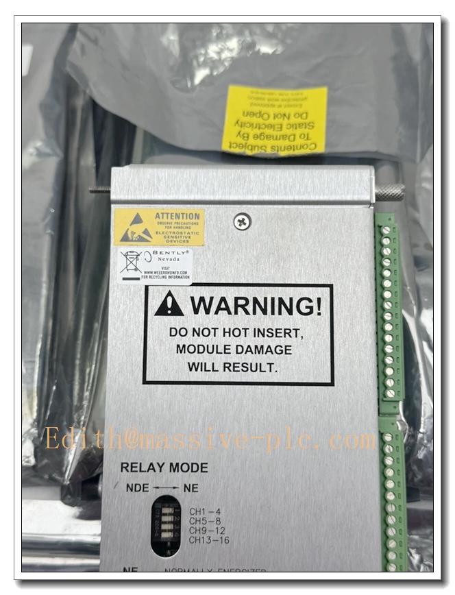
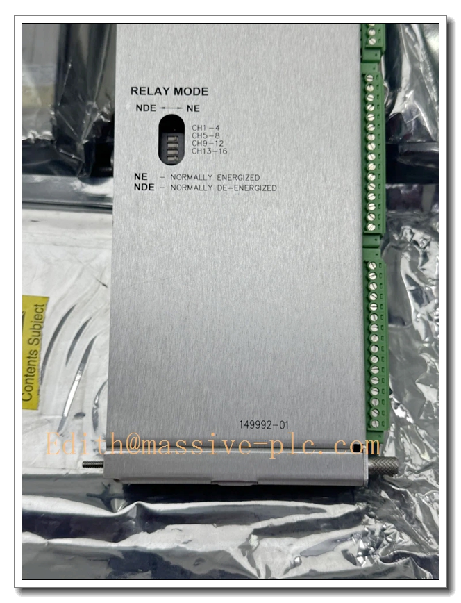
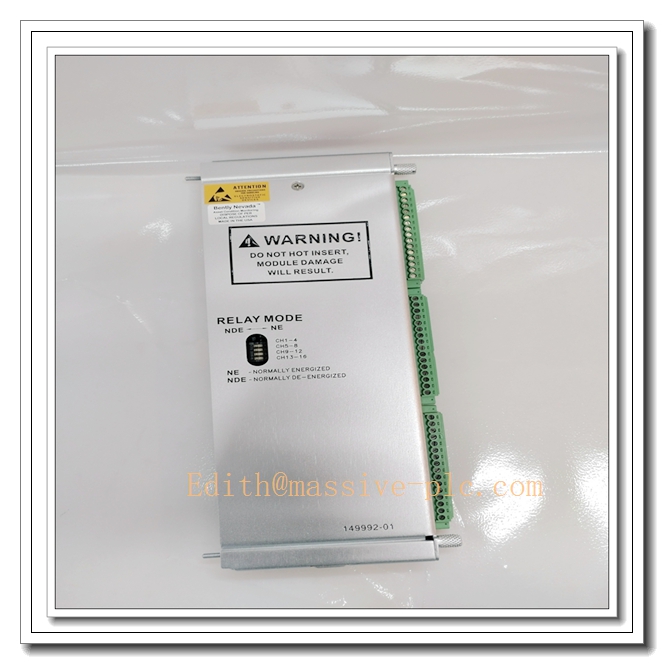
The 149992‑01 is the rear I/O relay output assembly for the Bently Nevada 3500/33 16‑Channel Relay Module, which must be mechanically and electrically mated with the front control board 149986‑01 to form a complete functional relay unit. This rear assembly houses 16 SPDT dry‑contact relays, field wiring terminal blocks, and group‑selectable DIP switches for relay energization mode. It converts logic commands received from the front control module into hard‑wired dry‑contact outputs, serving as the physical field‑wiring interface between the 3500 machinery‑protection rack and external plant hardware such as annunciators, DCS/PLC discrete inputs, alarm panels and emergency shutdown circuits. It delivers alarm notification and machinery‑trip interlock signals for critical turbo‑machinery within the 3500 monitoring ecosystem.
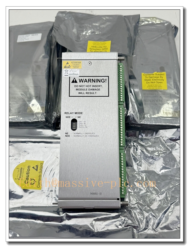
149992‑01
Technical Specifications
| Item | Parameter |
|---|---|
| Part Number | 149992‑01 (Rear Relay Output I/O Assembly for 3500/33) |
| Mandatory Mating Front Board | 149986‑01 |
| Relay Quantity & Type | 16 independent SPDT dry‑contact relays; channels can be paired for virtual DPDT operation |
| Contact Rating | Max 2 A @ 30 VDC resistive load |
| Group Configuration | 4 groups × 4 channels; DIP‑switch selectable: Normally‑Energized / Normally‑De‑Energized per group |
| Isolation | 1000 V RMS channel‑to‑channel; 150 V RMS field‑contacts‑to‑rack‑backplane |
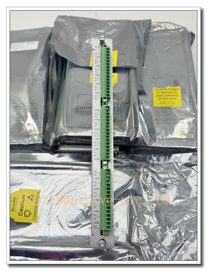
| Termination | Screw‑type field wiring terminal blocks on rear face |
| Power Source | Powered via rack backplane through mated front‑board assembly |
| Operating Ambient Temperature | ‑30 °C ~ +65 °C |
| Storage Temperature | ‑40 °C ~ +85 °C |
| Humidity | 5 %‑95 % RH, non‑condensing |
| Certifications | CE, UL, API 670 compliant |
| Mechanical | Full‑height rear I/O assembly for 3500 rack; hot‑swap compatible; weight approx. 0.45 kg |
| Configuration Tool | Bently Nevada 3500 Rack Configuration Software |
| Slot Requirement | Installed in rack slots to the right of the TDI / Rack Interface Module |
Main Features and Advantages
Key Features
- Sixteen SPDT dry‑contact relay outputs integrated on rear assembly; supports channel pairing to realize virtual DPDT contacts for high‑reliability trip circuits.
- Hardware DIP switches on the rear assembly permit per‑group selection of normally‑energized or normally‑de‑energized operation to match project safety‑circuit philosophy.
- High galvanic isolation separates field‑side relay contacts from rack backplane bus, mitigating ground‑loop interference and protecting monitoring electronics from field‑side surge and short‑circuit risks.
- Screw‑terminal field‑wiring interface provides robust connection for plant alarm and trip wiring.
- Hot‑swap capable when mated with matched front board; full assembly can be replaced without rack power‑down.
- Works in conjunction with front‑board programmable AND / OR voting logic, responding to Alert, Danger, Not‑OK and Bypass status from all monitor modules within the same 3500 rack.
- Multiple 149992‑01 + 149986‑01 assemblies can be fitted in one rack to expand total relay output capacity for large machinery‑protection systems.
Core Advantages
- Provides reliable hard‑contact interface between TSI monitoring rack and external safety‑instrumented systems, eliminating the need for bulky external auxiliary relay cabinets.
- Hardware‑selectable energization modes support both de‑energized‑to‑trip and energized‑to‑trip safety‑design schemes.
- High‑isolation design prevents field‑side electrical faults from propagating into sensitive 3500 monitor electronics.
- Matched front‑rear assembly design simplifies spare‑part management and hot‑swap maintenance, reducing plant downtime.
- Fully compliant with API 670 turbo‑machinery protection standards for oil‑gas, petrochemical and power‑generation critical rotating assets.
Application Fields
- Oil & Gas: centrifugal compressors, gas turbines, steam turbines; dry‑contact outputs for ESD shutdown, machinery alarm and annunciator‑panel signalling.
- Power Generation: thermal‑power and combined‑cycle plants; turbine‑generator safety interlock and alarm status transmission to DCS / PLC systems.
- Petrochemical: turbo‑expanders, large process pumps and blowers; execution of machinery‑protection alarm and trip logic.
- Heavy Industry: steel, cement and mining facilities for critical rotating‑machinery alarm and interlock control.
- General rotating‑machinery protection: convert digital monitor‑system alarm status into hard‑wired discrete signals for safety instrumented systems and local alarm devices.
Related Product Recommendations
- 149986‑01: 3500/33 front‑plane control board, mandatory mating part for 149992‑01.
- 149992‑02: Alternate rear I/O assembly, failsafe‑optimized relay version for safety‑critical trip loops.
- 3500/32M: 4‑channel relay monitor module for applications requiring fewer hard‑contact outputs.
- 3500 system accessories: 3500/05 rack chassis, 3500/15 redundant power supply, 3500/92 communication gateway.
- Companion monitor modules: 3500/42M vibration monitor, 3500/61 temperature monitor, 3500/62 process‑variable monitor, providing alarm trigger sources.
Installation and Maintenance
Installation
- Physically mate the 149992‑01 rear I/O assembly with the 149986‑01 front control board; insert the combined full‑height unit into a valid slot located to the right of the rack interface module inside the 3500 rack, and fasten front‑panel locking screws.
- Connect external field circuits (trip solenoids, annunciators, DCS discrete inputs) to rear‑assembly screw terminals. Strictly respect relay contact voltage and current ratings; avoid contact overload.
- Configure DIP switches on 149992‑01 rear assembly to set normally‑energized / normally‑de‑energized mode for each four‑channel group according to project safety specifications.
- Use 3500 Rack Configuration Software to define voting‑logic conditions for each relay channel, assign alarm trigger sources from corresponding monitor modules, and download configuration to rack backplane.
- Verify front‑panel LED status of 149986‑01; solid OK lamp indicates normal module operation. Perform full relay‑simulation test before commissioning to validate alarm‑trigger and contact‑actuation behaviour.
Maintenance
- Hot‑swap replacement is supported: set relevant alarm channels to bypass status before extracting the complete front‑rear assembly; install a complete matched set of new 149986‑01 + 149992‑01; reload configuration parameters as needed; rack power‑off is not required.
- Periodically inspect rear‑assembly wiring terminals for looseness, oxidation or corrosion; verify contact load conditions to prevent relay‑contact over‑current damage.
- Routinely check front‑panel LED indicators of the mated 149986‑01; investigate fault or abnormal relay‑status indications promptly.
- Maintain unobstructed rack ventilation; ensure operating temperature and humidity remain within rated ranges.
- Conduct periodic functional testing: simulate monitor‑module alarm conditions to verify correct relay‑actuation performance.
- For defective hardware, return the complete front‑rear assembly to authorized service channels; do not disassemble internal relay circuits on‑site.

 Start Chat




