
Description
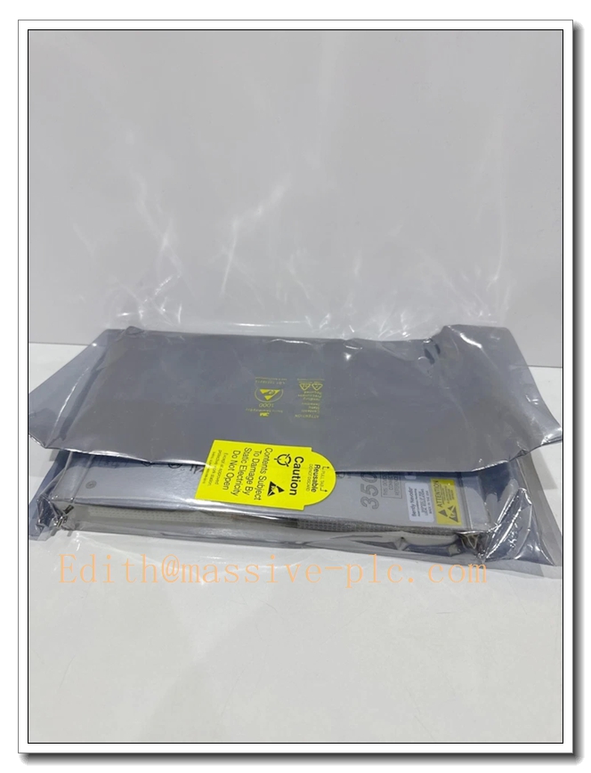
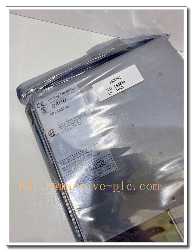
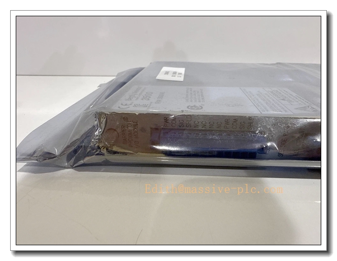
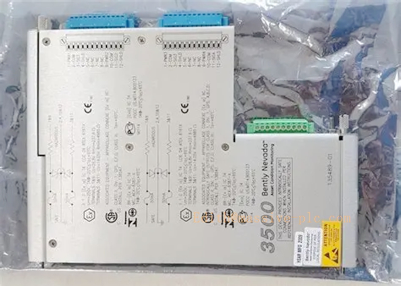
Bently Nevada 135489‑01 (3500/42M Internal‑Barrier I/O Module, 4×Prox/Accel, Internal Termination)
Product Description
135489‑01 is the rear I/O assembly for the Bently Nevada 3500/42M Proximitor/Seismic Monitor with built‑in intrinsic‑safety internal barriers. It mates with the 176449‑02 front monitor board to form a complete 3500/42M‑04‑00 monitoring unit. This I/O module provides intrinsically‑safe field interfaces for four channels of eddy‑current proximity probes and accelerometers, permitting direct wiring of sensors located in hazardous explosive classified areas (Zone 0 / Zone 1) without separate external safety barriers. It handles field signal termination, intrinsic‑safety energy limiting, and signal routing to the 3500 rack backplane. It supports radial vibration, thrust position, differential expansion, eccentricity, REBAM, acceleration measurements for turbo‑machinery protection and predictive‑maintenance workflows. Internal termination design means field cables connect directly to the rear module terminals, eliminating separate external termination boards。
135489‑01
Technical Specifications
| Item | Parameter |
|---|---|
| Part Number | 135489‑01 |
| Function | 3500/42M I/O Module with Internal Intrinsic‑Safety Barriers, Internal Termination |
| Channel Configuration | 4 channels: Proximity Probe / Accelerometer input (4 × Prox/Accel) |
| Compatible Front Board | 176449‑02 (3500/42M front monitor) |
| Supported Sensors | 3300XL eddy‑current proximity probes, accelerometers (IS‑certified sensors required for hazardous‑area deployment) |
| Intrinsic‑Safety Rating | ATEX / IECEx intrinsic‑safety certified for hazardous‑area transducer connections |
| Termination Type | Internal termination; field cables connect directly to I/O module terminals |
| Buffered Output | Buffered transducer BNC outputs located on front‑panel of paired 176449‑02 module |
| Power Consumption | Power supplied via rack backplane (I/O assembly draws no additional independent power) |
| Operating Ambient Temperature | 0 °C ~ +65 °C (with internal barrier active) |
| Storage Temperature | ‑40 °C ~ +85 °C |
| Humidity | 5 %‑95 % RH, non‑condensing |
| Certifications | ATEX, IECEx, CE, UL, compliant with API 670; compatible with SIL 2 system architecture |
| Mechanical | Full‑height rear I/O assembly for 3500 rack; hot‑swap compatible; weight approx. 0.46 kg |
| Configuration Tool | Bently Nevada 3500 Rack Configuration Software |
Main Features and Advantages
Key Features
- Integrated intrinsic‑safety internal barriers: built‑in energy‑limiting circuits enable direct connection to IS‑rated sensors in hazardous zones, removing requirement for bulky external safety barrier cabinets.
- Four‑channel Proximity / Accelerometer input configuration with internal termination; field wiring terminates directly on this rear assembly, reducing intermediate junction points and wiring complexity.
- Strict system‑level intrinsic‑safety certification: barriers and monitor are certified as a matched system; no manual barrier‑sensor parameter‑matching calculation required on site.
- Hot‑swap‑capable paired assembly (176449‑02 front + 135489‑01 rear); full unit can be replaced without rack power‑down.
- Fully interoperable with standard 3500 rack backplane; supports TMR triple‑modular‑redundant deployment for high‑safety turbo‑machinery projects.
- Mixed‑mode rack coexistence: barrier‑equipped 3500/42M assemblies may occupy slots within the same rack alongside standard non‑barrier 3500 monitor modules.
Core Advantages
- Eliminates external intrinsic‑safety barrier hardware, cuts cabinet space, reduces spare‑part stock and overall project capital cost for hazardous‑location machinery‑protection installations.
- Internal‑termination design lowers field‑wiring failure risk by minimizing intermediate terminal connections.
- Matched factory‑certified barrier‑monitor‑sensor system reduces engineering risk and simplifies hazardous‑area approval documentation.
- Maintains full 3500/42M measurement performance; barrier circuitry does not degrade vibration‑measurement accuracy or frequency‑response characteristics.
- Complies with API 670 turbo‑machinery‑protection standards for oil‑gas, petrochemical and power‑plant critical rotating‑equipment.
Application Fields
- Oil & Gas: offshore platforms, on‑shore compressor stations; centrifugal compressors and gas turbines with transducers installed in ATEX/IECEx hazardous zones.
- Petrochemical: refineries, ethylene plants; turbo‑expanders, large process pumps and blowers with sensors located inside classified explosive areas.
- Power Generation: gas‑fired combined‑cycle plants; turbine‑generator vibration and thrust‑position monitoring for hazardous‑classified machinery compartments.
- Heavy‑process industry: chemical plants where rotating‑machine sensors are mounted within Zone 0 / Zone 1 hazardous locations.
- Safety‑critical rotating‑machinery protection: vibration, thrust position and acceleration monitoring for ESD interlock and predictive‑maintenance in explosive‑atmosphere environments.
Related Product Recommendations
- 176449‑02: 3500/42M front monitor board, mandatory pairing part for 135489‑01.
- 135489‑02: Alternative internal‑barrier I/O module: 2 × Prox/Accel + 2 × Velomitor channels.
- 135489‑03: Internal‑barrier I/O module with four Velomitor‑optimized channels.
- 3500 system accessories: 3500/05 rack chassis, 3500/15 redundant power supply, 3500/33 relay module, 3500/92 communication gateway.
- Matching IS‑sensors: intrinsically‑safe 3300XL proximity probes, IS‑rated accelerometers for hazardous‑area installation.
- Companion monitors: 3500/61 temperature monitor, 3500/62 process‑variable monitor for complete machinery‑health supervision.
Installation and Maintenance
Installation
- Mate the 135489‑01 rear I/O assembly with the 176449‑02 front monitor board; insert the complete combined unit into a full‑height slot of the 3500 rack. For TMR redundant applications install three identical paired assemblies in adjacent rack slots.
- Route intrinsically‑safe field sensor cables to the terminals of 135489‑01. Strictly segregate intrinsically‑safe wiring from non‑IS high‑voltage / high‑power cabling per ATEX/IECEx installation rules; follow single‑point grounding specifications.
- Only use sensors certified compatible with this internal‑barrier I/O module; do not connect non‑intrinsically‑safe transducers.
- Launch 3500 Rack Configuration Software, configure measurement functions, sensor sensitivity parameters, Alert / Danger alarm thresholds and filter settings; download configuration to rack backplane.
- Verify front‑panel LED status of 176449‑02; solid OK lamp indicates normal operation. Perform gap adjustment and signal simulation tests before commissioning to validate measurement accuracy and alarm‑trigger behaviour.
Maintenance
- Hot‑swap replacement supported: set relevant monitor channels to bypass status before extracting the complete front‑rear paired assembly. Insert new matched 176449‑02 + 135489‑01 assembly; reload configuration parameters as needed; rack power‑off is not required.
- Periodically inspect IS‑field wiring and I/O‑module terminals for looseness, corrosion, insulation damage. Strictly maintain IS‑cable separation requirements during any field‑work activity.
- Regularly inspect front‑panel LED indicators; investigate Alarm, Bypass or Fault status promptly.
- Keep rack ventilation pathways unobstructed; ensure operating temperature stays within 0 °C ~ +65 °C range for barrier‑equipped I/O assembly.
- Conduct periodic loop‑calibration tests: inject simulated vibration / displacement signals to verify measurement accuracy and alarm‑response performance.
- For defective hardware, return the complete paired front‑rear assembly to authorized‑service channels. Do not disassemble internal barrier circuits on‑site; disassembly voids intrinsic‑safety certification.

 Start Chat




