Description
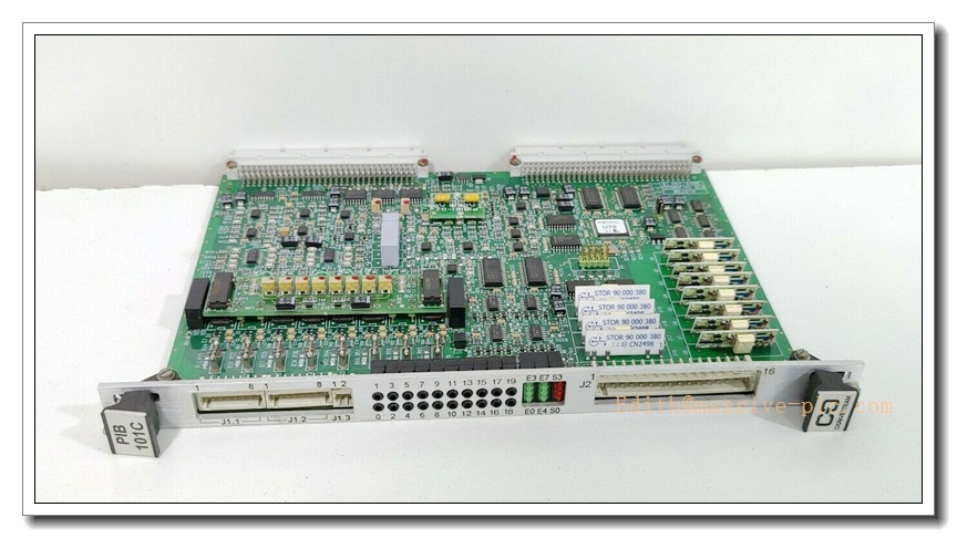
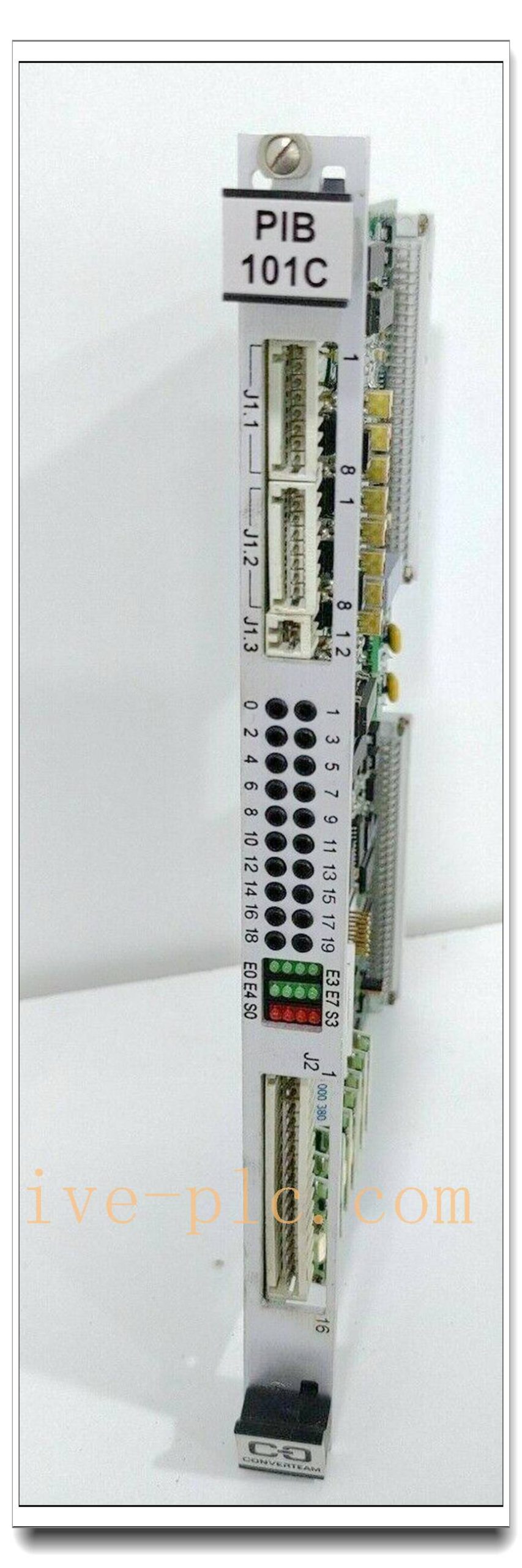
ALSTOM PIB101C Analog I/O Power Interface Board
Product Title
ALSTOM PIB101C (3BD91299) | VMEbus Analog I/O Power Interface Board for ALSPA / Converteam BGTR 8HE Rack
Product Description
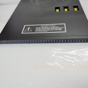
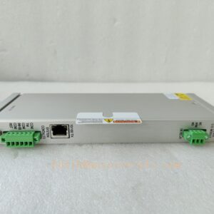
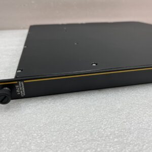
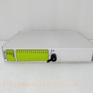
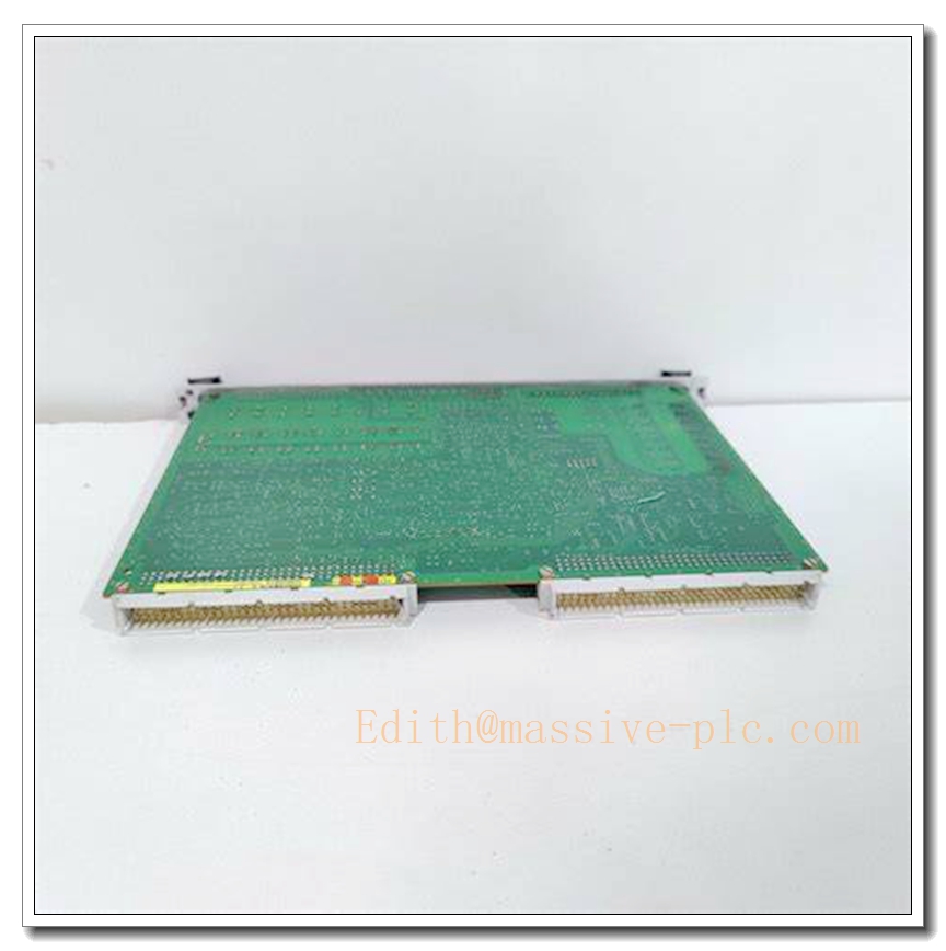
The ALSTOM PIB101C, part number 3BD91299, is a rugged VMEbus analog I/O power interface board developed for ALSPA and Converteam control systems. It acts as the bridge between field analog sensors, actuators and the VME backplane controller, integrating analog signal conditioning and rack power distribution functions. Equipped with an Intel Atom D2550 dual-core processor and hardware watchdog timer, the board delivers deterministic real-time signal acquisition and output regulation for high-reliability industrial control. It incorporates built-in circuit protection, continuous onboard diagnostics and noise suppression circuitry, making it suitable for continuous operation in harsh vibration and temperature environments. This legacy module is widely used for turbine control, power generation, marine propulsion and heavy-duty process control applications.
Technical Specifications
| Item | Parameter |
|---|---|
| Brand | ALSTOM (Converteam) |
| Model | PIB101C |
| Part No. | 3BD91299 |
| Board Type | Analog I/O Power Interface Board |
| Bus Standard | VMEbus, compatible with BGTR 8HE VME rack, P2/P0 backplane |
| Onboard CPU | Intel Atom D2550 dual-core, 1.86 GHz |
| Memory | 1×204-pin DDR3 SODIMM slot, up to 4GB |
| Storage | CFast industrial media slot + 2.5” SATA interface |
| Expansion | Mini PCI‑E, PC/104‑Plus |
| Watchdog | Hardware watchdog timer for system fail-safe |
| Operating Temperature | -20°C ~ +70°C |
| Storage Temperature | -40°C ~ +85°C |
| Humidity | 5% to 95%, non-condensing |
| Weight | 0.28 kg |
| Protection Class | IP20 (rack mounted) |
| Cooling | Passive heatsink cooling |
| Vibration Resistance | 5–150 Hz, amplitude 0.15 mm |
| Certification | CE, UL 508 |
Compatibility & Installation Pitfalls
Compatibility
- Rack: BGTR 8HE 8-slot VME rack with P2/P0 backplane
- System Platform: ALSPA H-Series, ControBloc / Converteam control system
- Matching modules: PIB100G, PIB310, UT150-1 rack power supply
- Configuration Tool: ALSPA engineering software suite
- Firmware: Must match the revision of the existing rack backplane and CPU controller
- Not compatible: Generic VME racks without P2/P0 backplane, third-party non-Converteam chassis
Critical Installation Traps
- Backplane slot mapping error: PIB101C requires fixed slot assignment on BGTR 8HE rack. Random slot placement triggers communication failure and loss of analog I/O.
- Backplane pin damage: VME P2/P0 connectors are fragile. Do not force insertion; bent pins will cause intermittent signal dropouts.
- Ground loop interference: Analog signal lines share the same protective earth with power cables. Large ground potential difference creates measurement drift and noisy analog readings. Separate signal ground and protective earth strictly.
- ESD vulnerability: High-density PCB and analog front-end circuits are ESD sensitive. Always wear anti-static wristband before handling the board; avoid touching gold-plated edge connectors.
- Mismatched firmware revision: Even if the board physically fits, mismatched firmware leads to backplane handshake failure and board fault alarms. Verify revision code before replacement.
- Poor thermal management: Passive cooling design. Blocked rack ventilation causes overheating, watchdog resets and premature board failure. Maintain rack airflow.
- Hot-swap limitation: PIB101C does NOT support hot swap. Rack must be fully de-energized and locked out before removal or insertion.
Standard Operating Procedure (SOP)
- Pre-Install Inspection Execute LOTO procedure to fully power down the BGTR rack. Inspect for physical damage, cracked PCB or bent VME pins. Confirm board revision matches system BOM. Prepare ESD protection kit and multimeter.
- Slot Preparation Confirm designated VME slot on BGTR 8HE rack. Visually inspect backplane P2/P0 pins for bending or corrosion. Clean connector contacts if contaminated.
- Module Insertion Hold board by the front panel handles only. Align VME edge connectors with backplane guides. Push steadily until fully seated, secure front panel screws.
- Field Analog Wiring Route field sensor/actuator cables to the board terminal block. Use shielded twisted-pair cable for analog signals, connect shield at single grounding point. Perform continuity and insulation resistance test.
- Software Configuration & Download Launch ALSPA engineering software. Add into hardware tree, configure analog channel signal ranges and watchdog parameters. Download project to system controller.
- Power-Up and Commissioning Restore rack power. Wait for board self-test. Check front-panel LED indicators. Inject calibrated analog signals to validate each channel reading, verify watchdog fault response.
- Operation & Maintenance Monitor board health, signal quality and diagnostic logs via ALSPA HMI. Periodically inspect rack temperature and ventilation.
- Removal & Replacement Implement LOTO, cut rack power. Disconnect field wiring terminals. Remove front panel screws, extract board straight out. Install spare , repeat commissioning and channel calibration.
Application Scenarios
- Steam & Gas Turbine Control Systems
- Power Generation Plant Control & Monitoring
- Marine Propulsion & Vessel Automation
- Heavy Industry Motor Drive Control
- Petrochemical Analog Measurement & Control Loops
- Railway traction auxiliary control
- Water & Energy Distribution Automation
Supporting Components
- BGTR 8HE VME Rack
- P2/P0 VME Backplane
- UT150-1 Rack Power Supply
- PIB100G Power Interface Module
- PIB310 I/O Interface Module
- ALSPA Engineering Configuration Software
- Shielded twisted-pair analog signal cables
- Anti-static wristband and ESD mat
- Calibrated signal source for analog loop commissioning
- Terminal blocks and cable glands
Related Model Recommendations (10 Models)
- PIB100G: ALSTOM VME rack power supply interface board
- PIB310: Multi-channel I/O power interface board for BGTR rack
- UT150-1: Rack power supply module for ALSPA system
- PIB201: High-density analog input interface board
- PIB202: Analog output interface board
- MVAU1: ALSPA VME analog signal conditioning module
- DIM100: Digital input VME module for BGTR rack
- DOM100: Digital output VME module
- CPU101: ALSPA VME main controller board
- COM101: VME communication interface board