
Description
ABB 129740-002 Product Technical Manual
Product Core Introduction
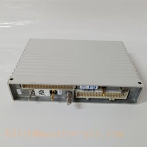
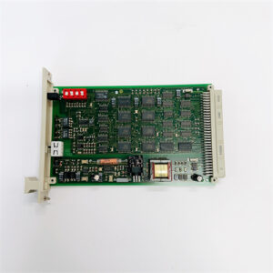
The ABB 129740-002 is an SIO Smart I/O Assembly spare part for ABB industrial control systems, used for signal acquisition and field I/O processing in heavy-duty process control racks. It acts as an intelligent interface between field sensors, actuators and the system backplane, performing signal conditioning, channel diagnosis and data forwarding. This module is widely adopted as an OEM spare replacement unit; its direct successor model is 129740-102. With built-in circuit protection and on-board diagnostic logic, it delivers stable signal transmission under vibration and electromagnetic interference in power, pulp & paper and metallurgy plants.
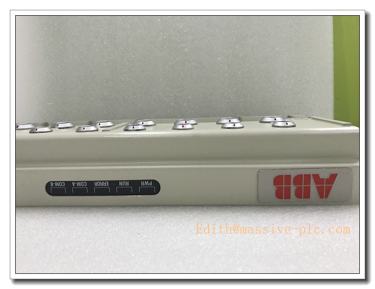
ABB 129740-002
Main Technical Specifications
- Model: 129740-002 (SIO ASSEMBLY/-102)
- Power Supply: 24VDC nominal, operating range 18–30VDC
- Channel Type: Multi-channel smart I/O with isolated field interface
- Backplane Interface: ABB proprietary rack bus
- Operating Temperature: 0°C ~ +60°C
- Storage Temperature: -40°C ~ +85°C
- Relative Humidity: 5%–95% RH, non-condensing
- Isolation Voltage: 1000V AC between field side and control logic
- Protection: Over-current, over-voltage and short-circuit protection per channel
- Protection Class: IP20 (for cabinet installation only)
- MTBF: ≥90,000 hours
- Mounting: Rack slot mounting
- Net Weight: 6.4 kg
- Certifications: CE, UL, RoHS compliant
- Status Indicator: Power, Run, Channel Fault, Bus Fault LED indicators
Recommended Homologous Series Models
- 129740-102: New upgraded replacement of 129740-002, improved EMC filtering and component lifespan, fully form, fit and function compatible.
- 129741-001: Extended SIO assembly with additional analog channels, suitable for sites requiring more 4–20mA measurement points.
- 129742-003: High surge variant SIO assembly, reinforced surge suppression for power plant and high EMI environments.
- 129743-002: Redundant paired SIO assembly, used for safety-critical control loops with hot backup.
Professional Quality Control & Test Standard Operating Procedures (SOP)
4.1 General Test Standard
All 129740-002 assemblies are inspected in accordance with ISO9001, IEC61131 and IEC61000 EMC standards. Each unit carries a unique serial number for full traceability.
4.2 Core Test SOP
- Visual & Mechanical Inspection: Inspect housing, PCB, terminal blocks and backplane connectors for scratches, cracks, solder defects and bent pins; verify mechanical dimensions and rack compatibility against engineering drawings.
- Power-On Basic Function Test: Apply minimum, rated and maximum 24VDC supply; validate power, run and fault LED behaviour; check for over-current or short-circuit events.
- Channel Signal Test: Inject simulated field signals to every I/O channel; confirm accurate signal sampling and output driving, no channel dropout or cross-talk.
- Backplane Bus Communication Test: Insert module into test rack; verify stable cyclic data exchange with controller, check bus error counters.
- EMC Immunity Test: ESD, electrical fast transient burst, surge and radiated interference test following IEC61000; ensure no false channel triggering or communication interruption.
- Temperature Cycling Test: 0°C ↔ +60°C thermal cycling for 40 cycles, 2 hours per cycle; check signal drift and connector stability.
- Vibration & Shock Test: 10–150Hz sinusoidal vibration and mechanical shock test to validate solder joints and connector retention.
- Continuous Burn-In Aging: 160 hours burn-in at 55°C with full channel loading; monitor signal quality and temperature rise, screen intermittent faults.
- Final Inspection & Packing: Reset factory parameters, record serial number, use anti-static packaging and attach inspection certificate.
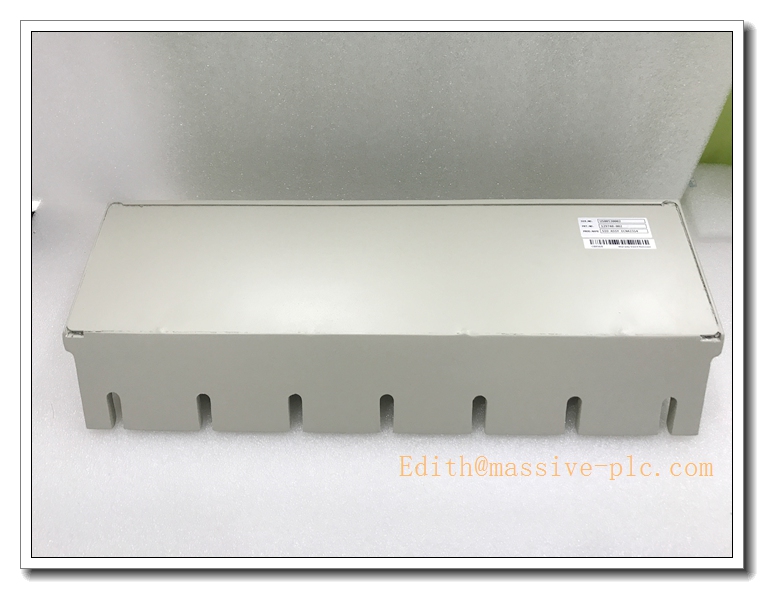
ABB 129740-002
New Module Installation Guidelines
5.1 Pre-installation Preparation
Cut off rack and backplane power; confirm model and serial number match the order; inspect anti-static package and connector integrity. Wear anti-static wristband before handling PCB components. Prepare screwdriver, torque driver and multimeter.
5.2 Installation Steps
- Open the target rack slot cover; carefully align the 129740-002 assembly with rack guide rails.
- Slide the module fully into the slot until the backplane connector is firmly seated.
- Fasten front panel retaining screws with specified torque to prevent loosening under vibration.
- Wire field sensors and actuators to terminal blocks; separate field signal cables from high-power cables to reduce interference.
- Tighten terminal screws to recommended torque; confirm no bare copper exposure and correct wiring polarity.
5.3 Post-installation Commissioning
Restore rack power and power on the assembly; observe LED indicators to confirm power and run status normal. Launch engineering software to read module diagnostic information and perform point-by-point channel test. Run continuous 60-minute stability test; verify bus communication and channel responses before putting the module online.
Application Scenarios & Product Features
6.1 Core Application Scenarios
- Thermal power plant boiler and turbine auxiliary control systems
- Pulp & paper process DCS rack signal acquisition
- Metallurgy continuous casting and rolling mill control cabinets
- Cement plant kiln process monitoring and interlock control
- Petrochemical plant auxiliary control and field signal interface
6.2 Core Product Features
- Integrated multi-channel smart I/O assembly with built-in per-channel diagnostics
- Electrical isolation between field wiring and control backplane to block ground loop interference
- Comprehensive hardware protection against overvoltage, overcurrent and short circuit
- Rack-mounted design, directly compatible with ABB proprietary control rack system
- Real-time fault LED indication and remote diagnostic data via backplane bus
- Robust mechanical construction, suitable for continuous long-cycle operation in process industry
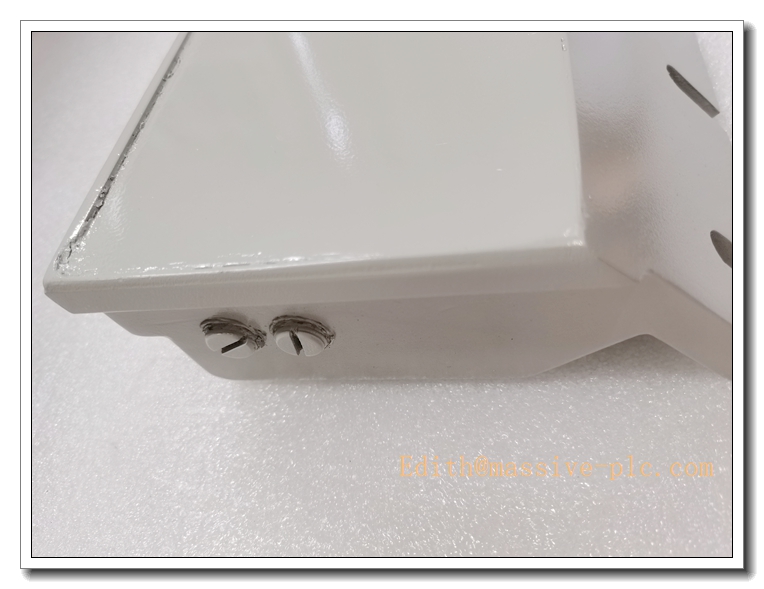
ABB 129740-002
Frequently Asked Questions (FAQ)
Q1: Power LED remains off after rack installation A1: Verify rack 24VDC power supply and polarity; inspect loose backplane contact or broken wiring; measure terminal voltage. If input voltage is normal and LED stays off, replace the assembly.
Q2: Some I/O channels show fault alarm A2: Check field wiring for short circuit or grounding; verify sensor/actuator power; swap channel terminals to distinguish between field device fault and module hardware damage.
Q3: Backplane bus communication intermittent drop-out A3: Re-seat the module in rack slot and tighten front panel screws; inspect backplane connector pins for oxidation; check for heavy EMI from nearby high-power cables.
Q4: Signal reading drift on analog channels A4: Check shielding grounding of field cable; eliminate ground loops; inspect terminal corrosion; recalibrate channels through engineering tool.
Q5: Module triggers over-temperature fault A5: Check cabinet ventilation and dust accumulation on PCB surface; confirm ambient temperature stays within 0~60°C; clean dust and restart.
Q6: Can 129740-002 be directly substituted by 129740-102? A6: Yes. 129740-102 is the upgraded replacement, form-fit-function compatible, direct swap without rack modification or program changes.


 Start Chat




