
Description
Core Product Introduction
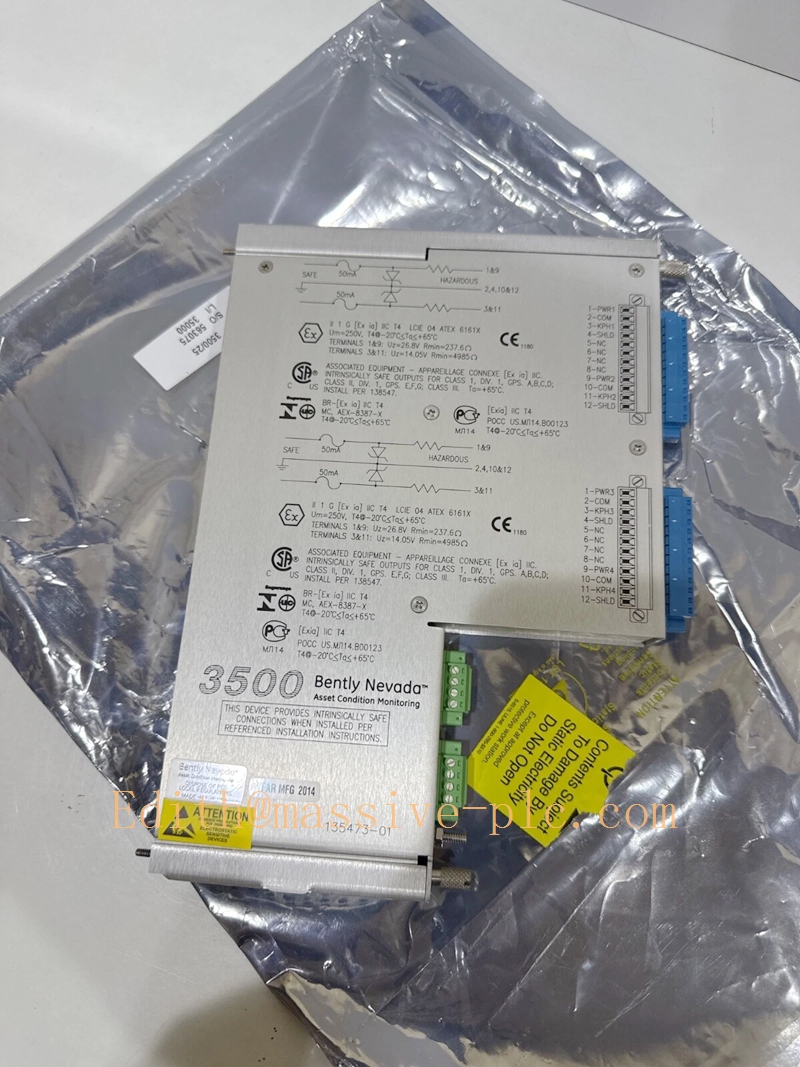
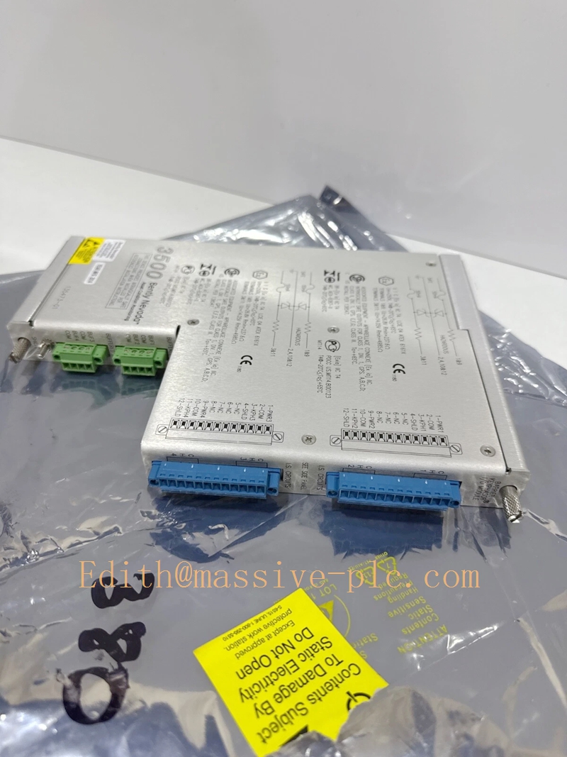
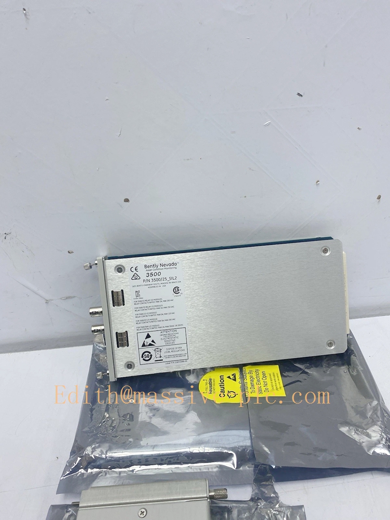
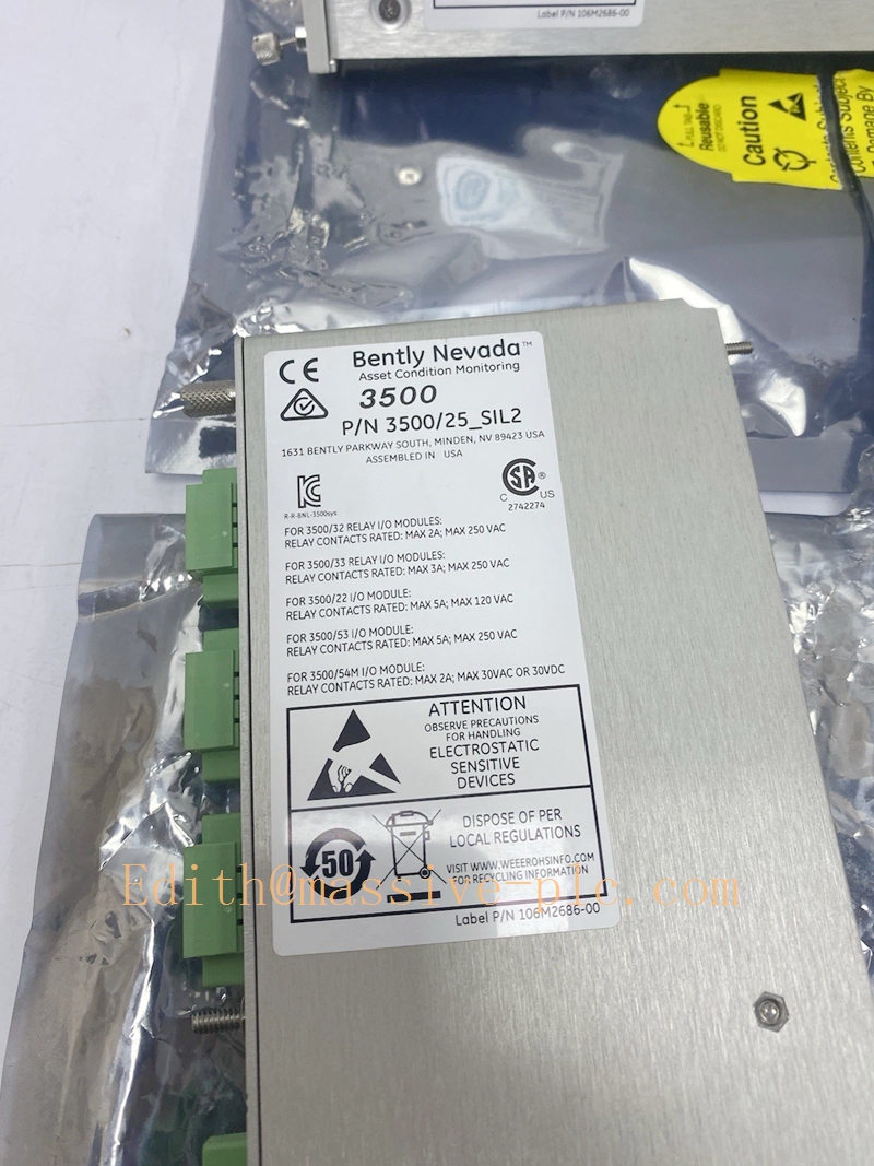
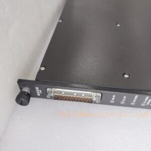
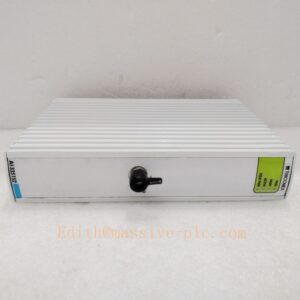
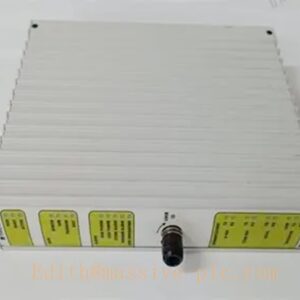
The Bently Nevada 3500/25-01-03-00, assembled with main logic board 149369-01 and integrated relay I/O sub-module 125800-01, is a dedicated 4-channel intelligent relay module built for the 3500 Machinery Protection System. It is designed to output independent, hardwired alarm and trip signals for critical rotating machinery, acting as the final safety execution layer between the 3500 monitoring rack and plant ESD, PLC or local annunciator systems. This module supports both latching and non-latching relay modes, and works seamlessly with all 3500 series monitoring modules to deliver reliable, SIL-rated protection response for high-priority industrial assets.
Main Technical Specifications
- Relay Channel Count: 4 fully isolated, form-C relay outputs per module
- Contact Rating: 250 V AC / 30 V DC, 5 A maximum resistive load
- Power Consumption: 6.8 W typical, 7.2 W maximum under full load
- Isolation Voltage: 2500 V AC between relay channels and backplane logic circuit
- Response Time: ≤ 10 ms from alarm trigger to relay contact state change
- Operating Temperature Range: -20 °C to +65 °C
- Hot Swap Support: Fully hot-swappable, no rack power interruption required during replacement
- Module Dimensions: Half-height 3500 series standard form factor, 203 mm × 108 mm × 38 mm
- Weight: 780 g nominal
- Compliance: Meets API 670, IEC 61508 SIL 2 and CE industrial EMC standards
Related Series Model Recommendations
- 3500/25-01-01-00 (149369-01 + 125800-02): Standard 4-channel relay variant with basic non-latching default configuration, ideal for general-purpose machinery alarm indication on non-safety-critical auxiliary pumps and fans.
- 3500/25-02-03-00 (149370-01 + 125800-01): 8-channel extended relay version, designed for large steam turbine supervision racks that require more independent trip and alarm output points without occupying extra rack slots.
- 3500/25-03-03-00 (149371-01 + 125801-01): Explosion-proof certified relay module with intrinsically safe output terminals, suitable for installation in Zone 2 hazardous areas in oil refineries and offshore platforms.
- 3500/32 133819-01: 4-channel relay module with built-in time delay function, used for anti-jitter trip logic that avoids false shutdowns caused by transient vibration spikes.
Professional Quality Control Test Standard Operating Procedure
- Visual & Identity Verification: Inspect module housing, front panel LED indicators and backplane connectors for physical damage, then cross-validate the serial numbers of 149369-01 and 125800-01 against Bently Nevada official part registry to confirm authenticity.
- Power-on Initial Test: Insert the module into a certified 3500 test rack, apply rated system power, verify all power and status LEDs illuminate in the correct sequence as defined in the factory startup manual.
- Individual Channel Functional Test: Send simulated alarm trigger signals from the rack configuration system to each of the 4 relay channels, use a multimeter to confirm every relay contact switches state correctly without delay or bounce.
- Load Endurance Test: Connect a 4 A resistive load to each relay output, run 1000 consecutive on-off cycles to validate contact reliability and no overheating occurs under rated load.
- Isolation Safety Test: Apply 2500 V AC dielectric withstand voltage between relay output terminals and the module backplane circuit for 60 seconds, confirm no breakdown or leakage current exceeds 1 mA.
- 72-hour Continuous Burn-in Test: Operate the module under 55 °C ambient temperature with all relays loaded, record status logs every 2 hours to ensure zero unplanned trip or communication dropout.
- Final Calibration & Release: Generate a full test report, attach a unique calibration label, and release the unit with a 12-month formal quality warranty certificate.
New Module Installation Guide
- Pre-installation Preparation: Power off the target 3500 rack slot logically via system software, confirm the new module part numbers 149369-01 and 125800-01 match the original BOM specification, and wear anti-static wrist strap before handling.
- Rack Slot Insertion: Align the module with the half-height guide rails on the left side of the 3500 rack, push it smoothly inward until the backplane connector is fully seated, then tighten the two front panel mounting screws to 0.8 N·m torque.
- Field Wiring Termination: Connect each relay output cable to the corresponding terminal on 125800-01 strictly following the site wiring diagram, separate high-voltage load cables from low-voltage sensor signal cables by at least 15 cm to avoid electromagnetic interference.
- System Configuration Upload: Launch the 3500 Rack Configuration Software, assign each relay channel to the corresponding vibration, position or speed monitoring parameter, set latching/non-latching mode and alarm delay time as required by the machinery protection logic.
- Post-installation Validation: Trigger each assigned alarm manually from the software, confirm the local annunciator, PLC and ESD system receive the correct relay signal, then lock the configuration and save a backup file to the site engineering archive.
Application Scenarios & Key Features
- Primary Application Scenarios: Main and auxiliary machinery protection systems in thermal power plants, centrifugal compressor supervision in petrochemical plants, large pump and fan safety interlock in water treatment facilities, and gas turbine condition monitoring in LNG terminals.
- Core Features:
- Every relay channel supports independent parameter mapping, allowing users to assign different alarm sources without cross interference.
- The module provides built-in relay fault detection, which automatically sends a diagnostic alert to the 3500 system if any relay coil or contact fails.
- It supports TMR redundant configuration when paired with two identical modules, meeting the highest safety requirements for critical turbine trip loops.
- The front panel LED for each channel clearly indicates alarm, trip and fault status, making on-site troubleshooting much more efficient for field engineers.
Frequently Asked Questions
- Q1: Can I replace an old 3500/25 module with this 3500/25-01-03-00 version directly without reconfiguring the whole rack?
- A: Yes, this version is fully backward compatible with legacy 3500/25 units, you only need to confirm the firmware revision of your existing rack TDI module supports the new part number before hot swap.
- Q2: What is the maximum load I can connect to the relay output?
- A: The rated maximum resistive load is 5 A at 250 V AC, for inductive loads such as large contactor coils, you must add an external surge suppression diode to extend relay service life.
- Q3: Does this module support latching alarm mode?
- A: Yes, you can configure latching or non-latching mode for each channel independently via the 3500 configuration software, latching mode will keep the relay tripped until manually reset by site operators.
- Q4: Can this module work in a TMR triple redundant protection rack?
- A: Yes, when installed in paired adjacent slots and configured with redundant logic, it can provide 2-out-of-3 voting relay output to eliminate single point of failure in critical trip loops.


 Start Chat




