Description
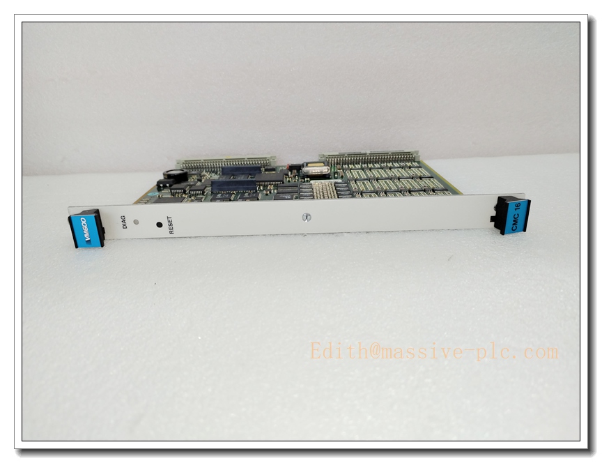
Meggitt VM600 CMC16 200-530-025-016? No, 200-530-025-014 16-Channel Condition Monitoring Card
Product Overview
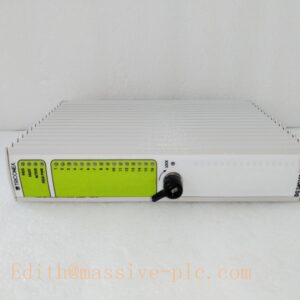
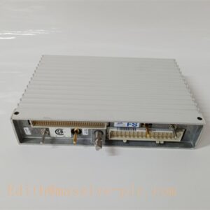
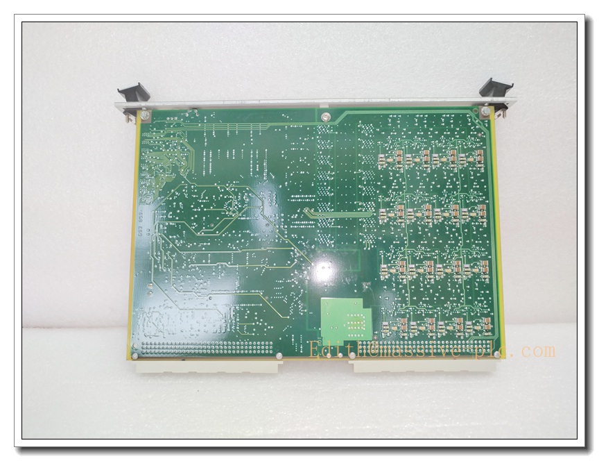
The Meggitt CMC16 (200-530-025-014) is a high-performance DSP-based condition monitoring card for the VM600 rack system, developed by Meggitt Vibro-Meter. It is the core signal acquisition & analysis module for rotating machinery health monitoring. The card acquires up to 16 dynamic sensor inputs, performs on-board real-time digital signal processing, FFT spectrum analysis, waveform and orbit calculation. It captures vibration, proximity, tacho speed and analogue process signals, supports transient event recording during machine trips or abnormal surges, and transmits processed data to VM600 host controller and CMS monitoring software. Installed in VM600 ABE04x / ABE056 6U racks, it works cooperatively with IOC4T / IOC16T I/O modules for continuous predictive monitoring in heavy-duty industrial environments.
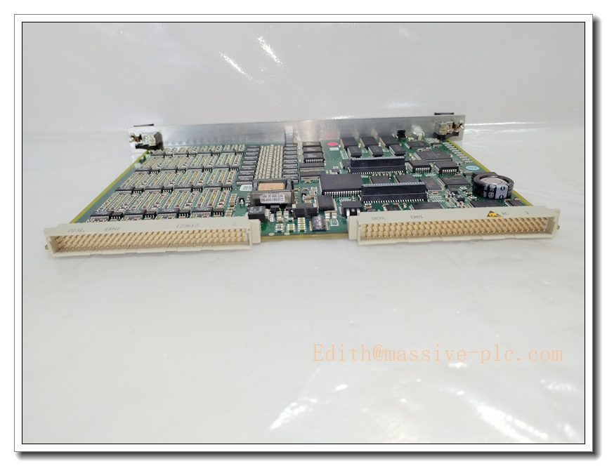
CMC16 200-530-013-012
Key Technical Specifications
- Part Number: 200-530-025-014
- Product Family: VM600 CMC16 Condition Monitoring Card
- Channel Count: 16 configurable dynamic input channels; first 4 channels support tachometer speed input
- Supported Sensors: Eddy current probes, IEPE accelerometers, velocity transducers, 4–20mA process transmitters
- Signal Processing: Onboard DSP, programmable anti-aliasing filters; up to 3200-line FFT resolution
- Sampling: Synchronous / asynchronous sampling, configurable sampling rate per channel
- Measurement Parameters: RMS, peak, peak-to-peak, spectrum, time waveform, shaft orbit, speed trend
- Communication: Backplane bus to CPU-M; Ethernet & RS485 serial interface for host data exchange
- Power Supply: Rack backplane powered, typical power consumption 15W
- Operating Temperature: -10°C ~ +60°C
- Mechanical: 6U VME form factor; Dimensions: 262 × 20 ×187 mm; Weight: 0.35 kg
- Mounting: Hot-swappable plug-in card for rack slots
- Diagnostics: Front-panel multi-color LED status, onboard self-test, sensor cable break detection
- Compliance: API 670, CE, suitable for SIL2 system integration (system-level assessment required)
Recommended 8 Similar Series Models ( family)
- Meggitt CMC16 200-530-022-014
- Meggitt CMC16 200-530-025-012
- Meggitt 200-530-025-016
- Meggitt IOC4T 200-512-040-001 ( I/O card)
- Meggitt IOC16T 200-512-160-001
- Meggitt CPU-M 200-500-001-014 ( main controller)
- Meggitt MPC4 200-510-071-113 ( protection card, your previous model)
- Meggitt RPS6U 200-504-001-001 ( rack power supply)
Quality Control & Test Standard Operating Procedure (SOP)
- Visual Inspection: Inspect PCB, front panel, connectors, solder joints and labels. Confirm part number and hardware revision match documentation, check for scratches, corrosion or physical damage.
- Continuity & Hi-Pot Insulation Test: Perform pin-to-pin continuity check. Insulation resistance test between power circuit and signal circuits to eliminate short-circuit risk.
- Power-Up Test: Apply rated rack power gradually. Verify power draw within rated range, LED boot sequence normal, no overheating.
- Built-in Self-Diagnostic Test: Execute internal self-test routine, confirm no fault codes reported.
- Channel Calibration Test: Inject reference vibration / tacho / analogue signals to each of the 16 channels. Validate linearity, gain accuracy, filter response and FFT spectrum output.
- Alarm & Event Logging Test: Simulate threshold crossing events, verify alarm triggering, transient waveform capture and on-board data buffer recording.
- Backplane & Communication Test: Insert card into rack, establish communication with CPU-M. Verify real-time data transmission and parameter download.
- Environmental Burn-in Test: Continuous burn-in under rated operating temperature for screening early failure components.
- Final Recheck & Documentation: Repeat key functional tests after burn-in. Generate full test report and serial traceability before packing for shipment.
New Module Installation Guide
- Pre-install Preparation: Power down rack fully. Wear ESD wrist strap and use anti-static mat. Confirm part number and hardware revision match the site BOM.
- Rack Slot Inspection: Check backplane connector for bent pins, dirt or oxidation. Clean slot guide rails.
- Card Insertion: Align card with rack guides. Slide smoothly into slot until backplane connector fully mates. Tighten front panel retaining screws evenly.
- Wiring Verification: Confirm all sensor cabling, shielding and earthing follow wiring diagram. Verify sensor types match channel configuration.
- Power Restore: Energize rack power supply. Observe front LED indicators to confirm normal boot.
- System Configuration & Commissioning: Connect CMS software, download channel setup parameters, configure sampling rates, filters and alarm thresholds. Perform channel injection test to validate signal reception.
- Post-install Check: Run full rack system self-test. Confirm no active faults. Save configuration file and complete installation commissioning records.
Application Scenarios & Features
Application Scenarios
- Gas turbine & steam turbine condition monitoring
- Centrifugal / axial compressors in petrochemical & LNG plants
- Turbo-generator sets for power generation
- Offshore rotating equipment monitoring
- Critical heavy-duty pumps, fans and gearboxes
- Predictive maintenance systems for high-value rotating machinery
Core Features
- 16-channel synchronous high-speed signal acquisition for multi-point machine health monitoring
- Onboard DSP processing: spectrum, waveform, orbit calculation locally to reduce host load
- Transient capture function for recording machine trip, surge and abnormal events
- Programmable anti-aliasing filters and flexible sampling configuration per channel
- Hot-swap capable for maintenance without full rack shutdown (system dependent)
- Built-in sensor fault and cable break diagnostics
- Supports predictive trend tracking for early equipment degradation warning
- Native integration within Meggitt machinery monitoring ecosystem
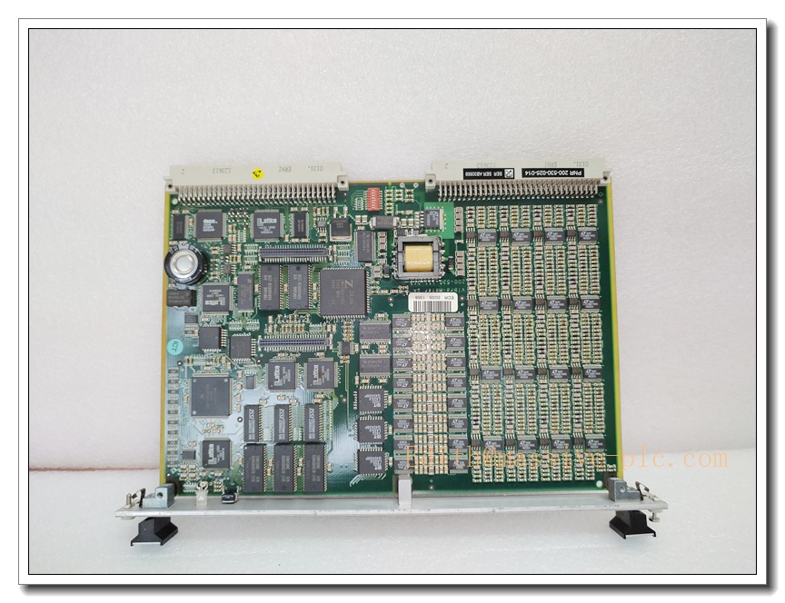
CMC16 200-530-013-012
FAQ
Q1: What is the difference between and MPC4?
A1: is a Condition Monitoring Card, focused on high-resolution vibration spectrum, waveform, orbit analysis and predictive trending. MPC4 is a Machinery Protection Control Module, mainly for real-time protection alarm and relay trip logic. They work together inside rack, serving different functions.
Q2: Can be hot swapped?
A2: The hardware supports live insertion/removal. But hot swap is subject to the overall system configuration. It is not recommended to perform hot swap while the protected machine is running in critical operating state.
Q3: What to do if channel faults appear after installation?
A3: Check sensor cable continuity, shielding and grounding. Run card self-test. Swap the into a known-good rack slot to isolate fault source: module, wiring or sensor.
Q4: Is SIL2 certified?
A4: SIL rating applies to the complete machinery protection system, not standalone card. A full system safety assessment is required to achieve SIL2.
Q5: What is the recommended calibration interval?
A5: Under normal industrial environment, recommended calibration cycle is 12–24 months, subject to site safety requirements. Typical service life >10 years.
Q6: Which rack is compatible with 200-530-025-014?
A6: Designed for ABE04x and ABE056 series 6U racks, paired with CPU-M controller and IOC4T / IOC16T I/O modules. Check CPU-M firmware revision before replacement.
Q7: What sensors can connect to channels?
A7: Eddy current proximity probes, IEPE accelerometers, velocity sensors and 4–20mA process transmitters. First four channels support tachometer pulse input for shaft speed measurement.
Q8: Where is the signal analysis processed?
A8: Signal processing, FFT and waveform/orbit calculation run on the onboard DSP of . Only processed measurement data and captured transient records are transmitted to the host CPU-M and CMS software.