
Description
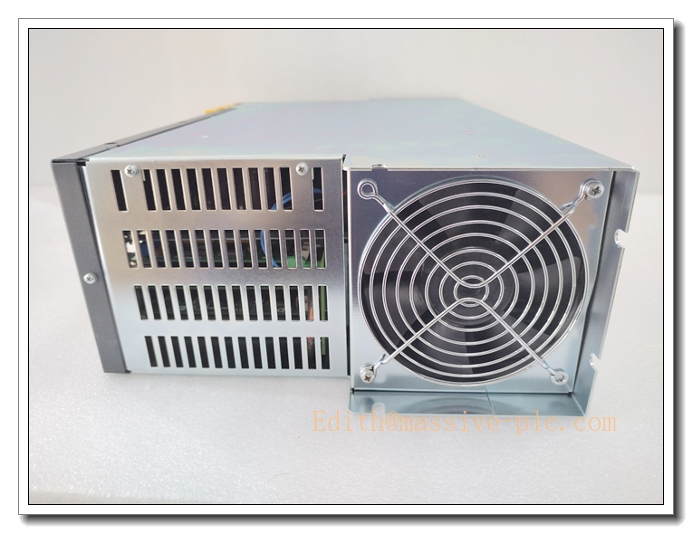
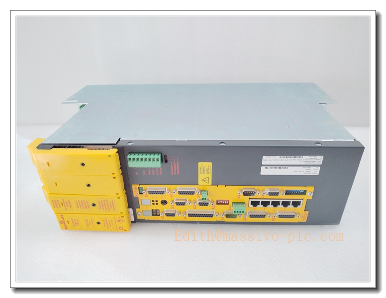
Baumüller BUM61-20/30-54-B-O-12 BUM61 Series Single Axis Servo Power Unit
Product Core Introduction
The BUM61-20/30-54-B-O-12 is a standalone servo power unit from Baumüller BUM61 family. The model coding 20/30 stands for 20A continuous output / 30A peak output; 54 refers to 540VDC DC-link. It works in combination with BUS6-VC control cassette to implement closed-loop torque, velocity and position control for synchronous AC servo motors. This unit accepts 3-phase 400~460VAC mains supply, featuring fast current loop response, integrated brake chopper and comprehensive fault protection. Widely used in printing machinery, textile lines, metal forming and special machine automation. This series is OEM end-of-life; available stock is fully tested refurbished & surplus spare units for legacy machine maintenance.
Main Technical Specifications
| Technical Parameter | Specification Value |
|---|---|
| Model | BUM61-20/30-54-B-O-12 (Baumüller) |
| Product Type | Single-axis servo power unit (requires BUS6-VC control card) |
| Continuous Output Current | 20 A |
| Peak Output Current | 30 A |
| DC Link Voltage | 540 VDC |
| Mains Input | 3×400–460 VAC, -15% ~ +15%, 48–62 Hz |
| Auxiliary Control Supply | 24 VDC ±20% |
| Output Frequency | 0 ~ 400 Hz |
| Control Cassette | BUS6-VC (separate, plug-in) |
| Control Modes | Torque / Velocity / Position control |
| Feedback | Resolver / Incremental encoder (depends on control card) |
| Protection | Overcurrent, overvoltage, undervoltage, overtemperature, motor stall, earth fault, E-stop |
| Operating Temperature | 0 ℃ ~ +45 ℃ (cabinet) |
| Storage Temperature | -40 ℃ ~ +85 ℃ |
| Operating Humidity | 5% ~ 85% RH, non-condensing |
| Mounting | Cabinet panel mount |
| Net Weight | ~13.4 kg |
| Dimensions | 500 × 300 ×140 mm |
| Compliance | CE, UL |
| Lifecycle Status | OEM Discontinued, aftermarket tested spare |
Brand Same‑Series Model Recommendation
- BUM61-10/20-54-B: Lower current variant, 10A continuous / 20A peak, for small servo axes.
- BUM61-30/45-54-B: Higher power version, 30A continuous /45A peak for heavy inertia loads.
- BUM61-40/60-54-B: Max current BUM61 power unit for large machine axes.
- b maXX 3000 / b maXX 5000: Modern Baumüller servo platform, recommended for long-term system migration.
Professional Quality Control Test Standard Operating Procedures (SOP)
5.1 Incoming & Visual Inspection
Inspect power IGBT modules, DC-link capacitors, cooling fan, terminal blocks and BUS6-VC card slot. Visual check for bulging capacitors, burnt PCB traces, cracked solder, connector pin damage. Insulation and hi-pot test for power circuits. Batch traceability records retained.
5.2 Low-Voltage Power-On Pre-Test
Apply 24VDC control supply. Verify power-on self-test, LED status, BUS6-VC card detection and communication handshake. Check fan rotation and abnormal heating before applying 3-phase mains.
5.3 Burn-in Test
72-hour cyclic powered burn-in at 40°C ambient. Run dynamic load cycles with matched servo motor. Monitor DC bus ripple, output current, temperature rise and fault logs. Units with intermittent trips, current ripple or thermal drift are rejected.
5.4 Full Functional Calibration & Parameter Test
Use power analyzer, encoder/resolver simulator and oscilloscope to calibrate current loop, velocity loop and position loop response. Validate all protection functions: OC, OV, UV, overtemperature, earth fault and emergency stop. Verify analog setpoint, encoder feedback and motion profile execution.
5.5 Environmental Stress Screening
Temperature cycling (0 ℃ ↔ +45 ℃), humidity soak and low-level random vibration per IEC 60068, to verify mechanical integrity and power stage stability simulating shipping and factory operation.
5.6 Final Acceptance Test
Full system test with BUS6-VC control cassette and matching Baumüller servo motor. Execute jogging, positioning, speed profiling and emergency shutdown test. Verify fault code reporting. Complete appearance, label and accessory inspection before anti-shock packing.
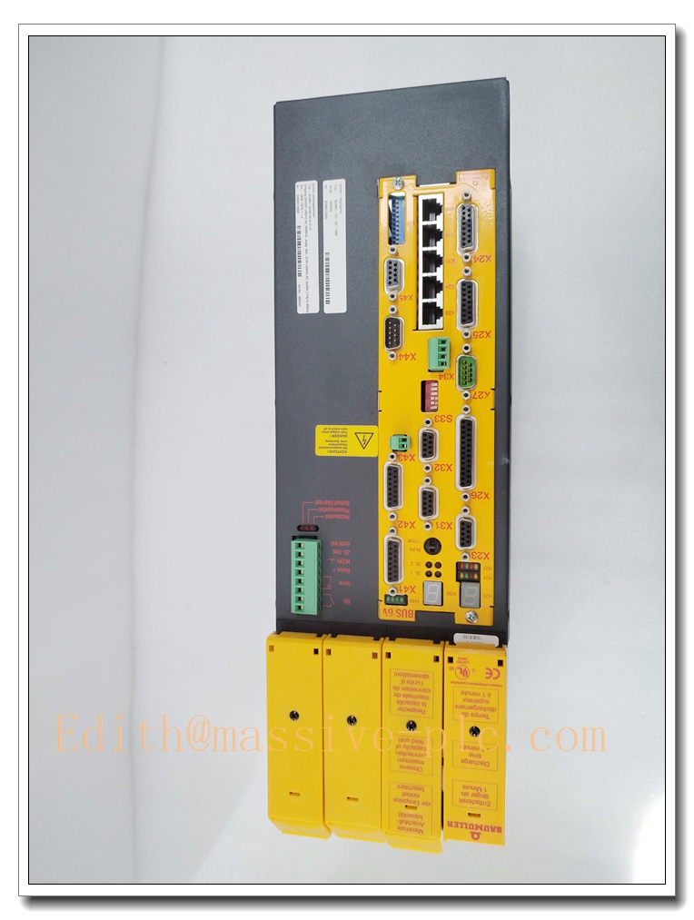
BUM61-20/30-54-B-O-12
New Unit Installation Guidelines
6.1 Pre-Installation Preparation
- Lock-out/tag-out (LOTO) the 3-phase mains supply. Confirm DC-link capacitors are fully discharged.
- Wear anti-static wristband and gloves; use anti-static mat when handling control card.
- Inspect unit for mechanical damage, capacitor swelling and bent terminals. Confirm compatibility with existing card and servo motor.
- Check cabinet cooling, fan clearance and grounding design.
6.2 Hardware Installation
- Mount the servo power unit on cabinet backplane, fasten mounting screws to specified torque and maintain required ventilation clearance.
- Insert control cassette into the slot and lock securely.
- Wire 3-phase mains, motor power cable, resolver/encoder feedback cable, 24VDC control power, analog command and E-stop interlock strictly following Baumüller wiring diagram.
- Use shielded cables for encoder and analog signals; separate low-level control wiring from high-power motor cables. Ensure protective earth connection is low impedance.
6.3 Post-Installation Commissioning
- Double-check wiring, grounding and interlock continuity before energizing.
- Apply 24VDC control power first, run self-test and check fault LED status.
- Energize 3-phase mains, input motor nameplate parameters and run motor identification auto-tune.
- Perform low-speed jog test, verify encoder/resolver direction and position feedback. Tune current, velocity and position servo loops.
- Run continuous motion profile test for 30–60 minutes before releasing machine to production.
Important Safety Note: This unit contains high-voltage DC-link capacitors. Hazardous residual voltage remains after power-off. Only qualified automation technicians can perform installation and service.
Application Scenarios & Product Characteristics
7.1 Application Scenarios
- Printing & converting machinery, web handling lines
- Metal cutting, bending and forming machine tools
- Textile high-speed automation equipment
- Packaging, handling and gantry automation systems
- Legacy Baumüller machine maintenance spare replacement
7.2 Key Characteristics
- Modular architecture: separate power unit + plug-in control cassette
- 20A continuous / 30A peak output for high dynamic acceleration
- 540V DC-link design for 400V class industrial servo motors
- Integrated brake chopper for regenerative energy handling
- Multi-layer protection for overcurrent, earth fault and over-temperature
- Supports resolver or incremental encoder feedback
- Robust cabinet design for continuous 24/7 factory operation
- Critical spare for legacy Baumüller motion systems (OEM discontinued)
FAQ (Frequently Asked Questions)
Q1: Power on reports DC bus overvoltage fault. A1: Check 3-phase input voltage, line reactor and brake resistor connection. Verify deceleration ramp; inspect aging DC-link capacitors.
Q2: Servo jitters and position fluctuates during operation. A2: Check encoder/resolver cable shielding, grounding and connector pins. Re-tune servo loops. Check mechanical coupling backlash or axis binding.
Q3: Drive trips overcurrent during acceleration. A3: Confirm motor parameters match drive configuration. Inspect motor winding insulation and cable short circuit. Reduce acceleration rate or check mechanical friction.
A4: Check control cassette seating and slot contacts. Inspect card edge connector for oxidation. Confirm firmware compatibility between and power unit.
Q5: Can I replace BUM61-20/30-54-B-O-12 directly with BUM61-30/45-54-B? A5: Mechanical footprint is compatible, but current rating increases. Motor parameters and servo tuning must be revalidated.
Q6: Hot swap allowed? A6: NOT PERMITTED. Cut off all 3-phase power and fully discharge DC bus before opening enclosure or swapping control cassette.


 Start Chat




