Description
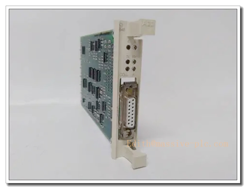
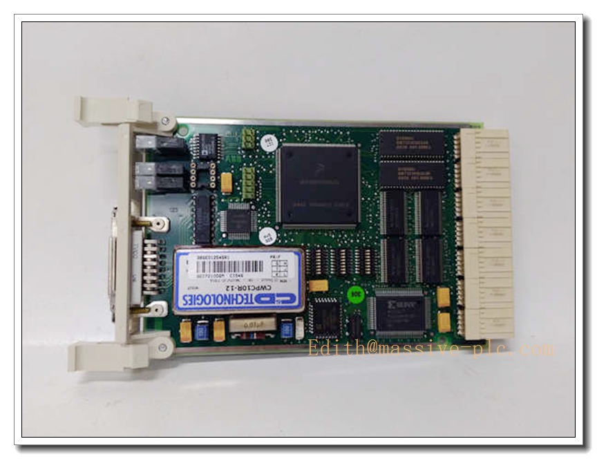
ABB CI545 Communication Interface Module | S800 I/O Bus Adapter Spare Part
Product Overview
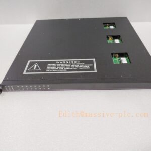
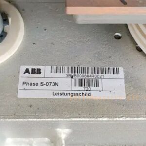
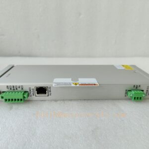
The ABB CI545 is a dedicated fieldbus communication interface card designed for S800 distributed I/O racks under System 800xA / AC800M control architecture. It establishes stable data exchange links between the AC800M controller and S800 I/O stations, handling cyclic process data, diagnostic feedback and parameter download for analog, digital and HART I/O modules. Widely deployed in power generation, pulp & paper, chemical, oil & gas and water treatment plants, this module serves as a critical spare to restore S800 I/O communication channels. It supports hot-swap replacement, on-board channel diagnostics and redundant bus configuration for high-availability control loops.
CI545
Key Technical Specifications
| Item | Parameter |
|---|---|
| Part Number | CI545 |
| Product Type | S800 I/O Communication Interface Card |
| Compatible Controller | ABB AC800M, System 800xA |
| Supported I/O Series | S800 I/O Modules (AI/AO/DI/DO/HART) |
| Bus Protocol | ModuleBus for rack communication |
| Mounting Style | Plug-in for terminal base unit |
| Supply Voltage | 24 V DC |
| Operating Temperature | 0 °C ~ +60 °C |
| Storage Temperature | -20 °C ~ +70 °C |
| Relative Humidity | 5% ~ 95 %, non-condensing |
| Enclosure Rating | IP20 (cabinet installation only) |
| Feature Support | Hot-swap, on-board LED diagnosis, fault alarm |
| Country of Origin | Sweden |
| Certification | CE, RoHS compliant |
Quality Control Procedure
- Visual & Label Inspection: Check PCB condition, connector pins, solder joints, LED indicators and laser marking; verify ESD packaging integrity.
- Power Bench Test: Apply rated 24 VDC supply, confirm power indicator, check for short circuit and abnormal current draw.
- Bus Communication Simulation: Connect to test rack, verify ModuleBus handshake, cyclic I/O data transmission and alarm reporting.
- Hot-swap Function Test: Simulate live replacement to validate seamless bus recovery without controller crash.
- Continuous Burn-in Test: 48-hour runtime test under rated temperature to screen intermittent communication failures.
- Compatibility Verification: Cross-test with common I/O modules and AC800M controller firmware revisions.
- Final QC & Packing: Record serial number and test log, seal in ESD shielding bag with foam cushion, attach inspection report.
Related Replacement & Companion Models (15 pcs)
- CI854B
- CI871
- CI845
- TU810
- TU830
- TU844
- AI810
- AI830A
- AO810
- DI810
- DO810
- DI801
- AO845
- FI830F
- PM866
Frequently Asked Questions
Q1: What is the function of ABB CI545?A: CI545 is the ModuleBus communication card. It bridges AC800M controller and I/O racks, transferring process I/O signals, fault diagnostics and configuration data.
Q2: Can CI545 support hot swap?A: Yes, it supports hot-swap in valid rack configuration. Replacement can be performed without shutting down the whole controller, but follow site lockout rules for safety.
A: No. CI854B is PROFIBUS DP interface, CI871 is PROFINET IO interface. uses native ModuleBus for rack internal communication, not fieldbus. Confirm BOM before ordering.
A: rack offline alarm, loss of I/O communication, flickering communication LED, intermittent I/O freezing while controller remains running.
Q5: What is the warranty term?A: Standard 12-month warranty for functional defects. Warranty excludes damage caused by ESD, overvoltage, reverse wiring, water ingress or improper installation.
Installation & Configuration Guide
Precaution: Wear ESD wrist strap all the time during handling. Static discharge can permanently damage the communication chip.
- Preparation: Prepare anti-static mat, screwdriver, check 24 VDC power circuit and controller status. Lock & tag hazardous high voltage circuits.
- Identify Slot: Locate the communication slot on terminal base. Confirm slot position matches control system hardware configuration.
- Module Removal: Release the locking latch of old , pull it straight out gently from the base.
- Pre-check New Module: Inspect edge connector pins for bending, dirt or corrosion; confirm model marking matches your spare list.
- Insert & Lock: Align module guide rails, push firmly until fully seated, lock the latch. Ensure no loose contact.
- Power & Initial Check: Keep 24 VDC supply on for hot-swap application. Watch RUN / COM LED status. Normal status shows steady RUN light and blinking communication light.
- System Configuration Verification: Open Control Builder / 800xA engineering station, download hardware configuration if required. Confirm all I/O channels come online without bus alarms.
- Loop Test: Trigger DI/DO and analog signals to verify bidirectional data transmission. Clear historical communication faults after successful commissioning.
- Asset Record: Log serial number, installation date, rack slot number and firmware version for plant spare management.