
Description
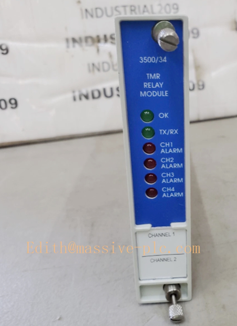
3500/34 (128034-01E) Bently Nevada TMR Relay Output Module Full Specification
Product Description
The Bently Nevada 3500/34 with part number 128034-01E is a high-reliability TMR (Triple Modular Redundant) relay output module designed exclusively for the 3500 machinery protection system. As a critical safety-level output card, it provides fault-tolerant relay voting logic to execute alarm and trip commands for rotating machinery protection. The module features four independent TMR relay output channels, adopting a 2-out-of-3 voting mechanism to eliminate single-point failure risks in protection loops.
Working in coordination with 3500 series monitoring modules, it converts internal system alarm and trip logic decisions into hard-wired relay contact outputs for interlocking with external PLC, DCS, ESD and emergency trip systems. Built for SIL-rated industrial safety applications, the 3500/34-128034-01E ensures high availability and low false-trip probability for turbine, compressor and generator protection systems operating under 24/7 continuous duty conditions.
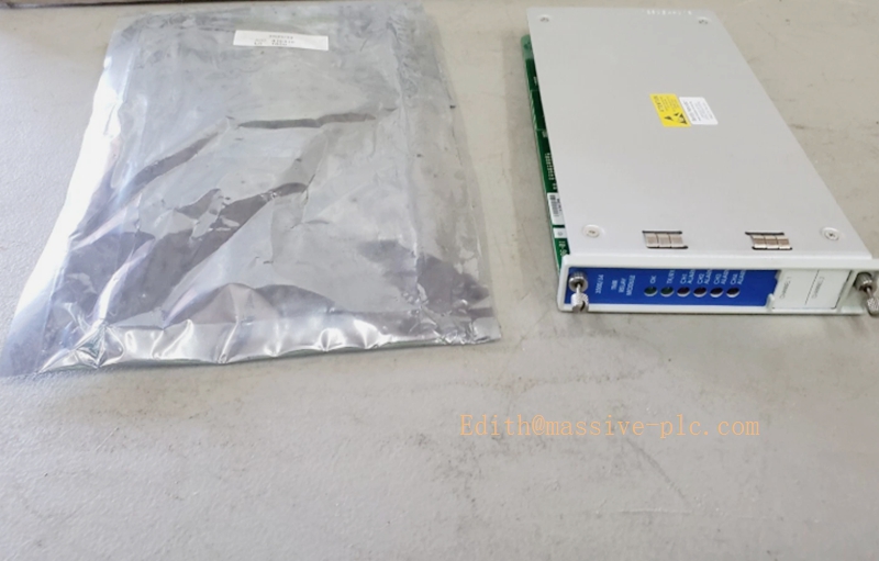
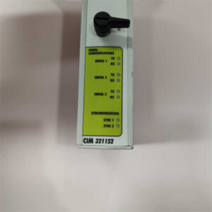
3500/34 128034-01E
Core Technical Specifications
| Model Number | 3500/34, Part No. 128034-01E |
| Module Type | TMR Triple Modular Redundant Relay Output Module |
| Output Channel Quantity | 4 independent configurable TMR relay channels |
| Voting Logic | 2-of-3 voting for each relay channel, single-fault tolerant |
| Contact Type | Form A / Form B configurable dry contact outputs |
| Contact Rating | Resistive load: up to 120 VAC / 30 VDC, standard industrial interlock rating |
| Response Time | Fast relay actuation with configurable alarm/trip delay parameters |
| System Interface | 3500 rack backplane bus communication, fully synchronized with monitor modules |
| Diagnostic Function | Built-in channel self-test, relay health monitoring and fault reporting |
| Safety Rating | Designed for machinery safety protection, compliant with API 670 and industrial SIL application requirements |
| Power Supply | Backplane-powered via 3500 rack redundant power supply |
| Operating Temperature | 0 °C to +60 °C |
| Storage Temperature | -40 °C to +85 °C |
| Installation Form | Standard 3500 series rack-mounted modular installation |
Key Features & Competitive Advantages
3.1 Core Features
- TMR Fault-Tolerant Architecture: Each output channel adopts triple modular redundant circuit design with 2-of-3 voting logic. Any single internal module or relay fault will not cause false trip or protection failure, maximizing system safety integrity.
- Four Independent Output Channels: Supports separate configuration for warning alarm, danger trip, auxiliary interlock and system fault indication, realizing multi-level and multi-function protection output management.
- Configurable Contact Logic: Flexible Form A normally-open and Form B normally-closed contact mode adaptation, compatible with various ESD, interlock and alarm loop design requirements.
- Comprehensive Self-Diagnosis: Real-time monitoring of relay coil status, contact integrity and channel circuit health. Automatically reports faulty channels and avoids invalid protection output caused by hidden failures.
- System Synchronized Operation: Closely matched with 3500 vibration/position monitor modules, ensuring consistent logic judgment and synchronous output of protection commands.
- Industrial Anti-Interference Design: Enhanced EMC electromagnetic compatibility design, stable output in high-noise industrial environments without contact jitter or misoperation.
3.2 Product Advantages
- Ultra-Low False-Trip Rate: TMR voting mechanism effectively filters transient system faults and interference signals, eliminating unnecessary equipment shutdowns and improving production continuity.
- High Safety & Reliability: Meets heavy-duty machinery protection standards, suitable for key equipment protection links that cannot tolerate protection failure.
- Excellent System Compatibility: Plug-and-play with all standard 3500 rack systems, no need for chassis or architecture modification during replacement or expansion.
- Centralized Protection Output Management: Concentrates all machine alarm and trip outputs on one module, simplifying on-site interlock wiring and facilitating system debugging and maintenance.
- Long-Term Operational Stability: Industrial-grade relay components and rigorous circuit design ensure long-cycle stable operation under continuous industrial working conditions.
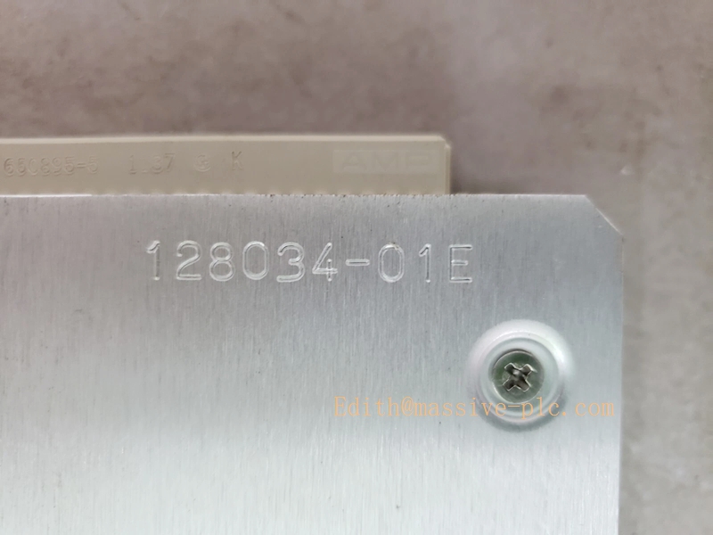
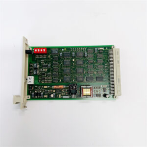
3500/34 128034-01E
Typical Application Fields
The 3500/34 128034-01E relay module serves as the core safety output unit for critical rotating machinery protection systems, widely applied in high-reliability industrial scenarios:
- Power Generation Industry: Turbine and generator vibration trip protection, bearing condition alarm, and unit interlock control in thermal power and gas power plants.
- Petrochemical & Refinery: Safety protection output for large centrifugal compressors, process pumps and high-speed rotating equipment, cooperating with ESD emergency shutdown systems.
- Oil & Gas Industry: Offshore and onshore process equipment machinery safety interlock and fault alarm output.
- Metallurgy & Heavy Industry: Protection signal output for large fans, rolling mills and high-power rotating equipment.
- High-Safety Industrial Projects: SIL-level safety monitoring and protection systems requiring fault tolerance and low false-trip performance.
- Legacy System Retrofit & Spare Replacement: Standard compatible spare part for existing 3500 rack systems, ensuring consistent protection logic after equipment renewal.
Technical Pitfalls to Avoid
- Misconfigured Voting & Delay Logic: Improper setup of channel voting parameters or protection delay may lead to failed fault response or delayed trip, risking equipment damage.
- Incorrect Contact Mode Selection: Confusing Form A and Form B contact settings will reverse alarm/trip logic, causing interlock failure or system abnormal shutdown.
- Overload Contact Operation: Exceeding rated contact voltage and current will cause relay contact ablation, sticking or permanent failure, resulting in protection loop failure.
- Ignoring Channel Self-Test Function: Disabling regular self-diagnosis will hide single-channel faults, leading to degradation of TMR fault-tolerant capability and loss of redundant protection.
- Backplane Power Instability: Fluctuating or unqualified rack power supply may cause module logic reset and intermittent relay misoperation.
- Non-Standard External Wiring: Unisolated high-power cables and ungrounded shielded wires introduce strong EMI interference, triggering accidental relay action.
- Mismatched Module Firmware: Mismatched firmware versions between 3500/34 and monitoring modules may cause logic synchronization errors and abnormal output.
Related Product Recommendations
- Bently Nevada 3500/33 Vibration Monitor Module: Matched vibration and position acquisition module, providing original fault judgment signals for 3500/34 output execution.
- Bently Nevada 3500/20 Rack Interface Module: Unified system communication and logic scheduling unit to ensure synchronous operation of all rack modules.
- Bently Nevada 3500/15 Power Supply Module: Redundant power supply unit to provide stable backplane power for TMR relay modules.
- 3300 Series Proximity & Velocity Sensors: Field sensing devices for machinery vibration and displacement monitoring, supporting complete closed-loop protection system construction.
- Bently Nevada 3500 System Configuration Software: Dedicated tool for relay channel logic configuration, delay setting, self-test activation and fault diagnosis.
- Isolated Safety Relay Terminal Accessories: Auxiliary isolation components to protect module contacts and improve external loop anti-interference capability.
Installation Guidelines
- Rack Installation Requirements: Install the module in a standard grounded 3500 industrial rack, placed in a temperature-controlled, dust-proof and dry electrical cabinet to avoid corrosive gas and strong vibration.
- Backplane Connection: Ensure firm card edge contact with the rack backplane; avoid loose insertion which may cause communication interruption and logic disorder.
- External Loop Wiring: Distinguish Form A/Form B contacts strictly during field wiring; separate protection signal wires from high-voltage power cables and adopt standard single-point shielding grounding.
- Parameter Configuration: Set independent alarm/trip delay and voting parameters for each channel according to equipment protection specifications, and match upper ESD/DCS interlock logic.
- Pre-Operation Simulation Test: Complete channel self-test, logic simulation and contact action verification after installation to confirm all protection output functions are valid and accurate.
Daily Maintenance Guidelines
- Routine Status Inspection: Regularly check module running indicators, relay channel status and wiring tightness; clean surface dust quarterly to ensure stable heat dissipation.
- Periodic Self-Test Execution: Manually trigger system self-diagnosis every six months to detect hidden faults in TMR channels and relay contacts in advance.
- Logic Calibration: Regularly verify the consistency between monitoring alarm logic and relay output action to avoid parameter drift causing protection deviation.
- External Loop Maintenance: Inspect external interlock loop insulation and aging status regularly, replace aging cables to prevent contact failure and signal leakage.
- Spare Module Management: Store standby modules in constant-temperature and dry environment; perform regular power-on tests to guarantee standby availability and functional integrity.


 Start Chat




